
Owner manual


42 Rockwell Automation Publication 20Y-UM001E-EN-P - July 2014
Chapter 1 AFE in IP20 2500 MCC Style Enclosure—Installation/Wiring
Table 5 - Recommended Control Wire for Digital I/O
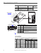
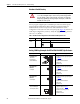
Figure 20 - Door Control Box I/O Terminal Blocks and Jumpers
I/O Terminal Blocks
Table 6 - Door Control Box I/O Terminal Block Specifications for AFE in IP20 2500 MCC Style Enclosure
Type Wire Type(s) Description Minimum
Insulation Rating
Unshielded Per US NEC or applicable national or local code —
300V, 60 °C
(140 °F)
Shielded Multi-conductor shielded cable such as Belden
8770(or equivalent)
0.5 mm
2
(22 AWG),
3 conductor, shielded
➋
➌
J1
J2
J3
J4
J5
➍
Components mounted on inside
of AFE enclosure (see Figure 12
for location)
See Table 6
below for door control box item number descriptions and specifications.
Door Control Box Components
X3 Term. No. Default Description
57 and 60 — Remote momentary pulse of 0.4…1.0 sec. across these terminals starts
precharge in REM mode when terminals 58 and 61 are remotely closed.
58 and 61 — These terminals must be remotely closed to start precharge. Opening
these terminals opens the main contactor K1.
63 and 64 — Remotely closing these terminals resets an AFE fault.
65 and 66 — AFE run signal to the inverter enable input.
400 and 480 480
Control input voltage setting.
600 and 690 690
For jumper configurations,
see Table 8 on page 45
.
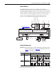
➊
(X3 Terminals)
No. Name Description Wire Size Range
(1)
(1) Maximum/minimum that the terminal block will accept - these are not recommendations.
Torque
Maximum Minimum Maximum Recommended
➊
Analog I/O Analog I/O Signals 2.5 mm
2
(14 AWG)
0.5 mm
2
(22 AWG)
0.2 N•m
1.8 lb•in
0.2 N•m
1.8 lb•in
➋
Digital Inputs Digital Input Signals 2.5 mm
2
(14 AWG)
0.5 mm
2
(22 AWG)
0.2 N•m
1.8 lb•n
0.2 N•m
1.8 lb•in
➌
Digital Outputs Digital Out Relays 2.5 mm
2
(14 AWG)
0.5 mm
2
(22 AWG)
0.5 N•m
4.5 lb•in
0.5 N•m
4.5 lb•in
➍
Control Terminal Customer input and
output control
2.5 mm
2
(14 AWG)
0.5 mm
2
(22 AWG)
0.8 N•m
7.1 lb•in
0.8 N•m
7.1 lb•in