
Owner manual

Rockwell Automation Publication 20Y-UM001E-EN-P - July 2014 37
AFE in IP20 2500 MCC Style Enclosure—Installation/Wiring Chapter 1
Routing the AC Input, Ground (PE), and DC Bus Output Wiring for AFE
in IP20 2500 MCC Style Enclosure
Frame 10
The AC input and ground (PE) wiring for the IP20 2500 MCC Style enclosure
must be routed through the top of the enclosure.
The DC bus output can be routed through either the left or right side of the
enclosure (see shaded areas in figure below).
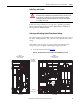
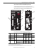
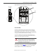
Figure 16 - Routing Areas for AC Input, Ground, and DC Bus Output Wiring for AFE
Frame 10 in IP20 2500 MCC Style Enclosure
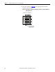
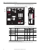
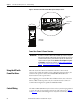
Frame 13
The AC Input and Ground (PE) wiring for the IP20 2500 MCC Style enclosure
must be routed through the top of the enclosure.
The DC bus output can be routed through either the left or right side of the
enclosure (see shaded area in figure below).
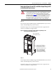
ATTENTION: To minimize disruption of air flow through the enclosure and avoid
overheating within the AFE enclosure, remove only the minimum area needed
to route the power cables. When removing any of the five side cover plates
(shaded areas shown in Figure 16
) for routing the AC input, ground (PE), and DC
bus output wiring, always use the Barrier Kit SK-Y1-MCCBARRIER to maintain air
flow integrity through the enclosure. Removing sections for routing in other
areas disrupts the air flow throughout the enclosure, causing overheating.
Area for routing AC input
and ground (PE) connections
Shaded areas for routing DC bus
output connections—on either the
left or right side of the enclosure
When the side cover plate is removed
for DC bus routing, always use the
Barrier Kit SK-Y1-MCCBARRIER to
maintain proper air flow in the AFE
enclosure and prevent overheating.