
Owner manual

22 Rockwell Automation Publication 20Y-UM001E-EN-P - July 2014
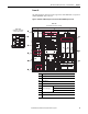
Chapter 1 AFE in IP20 2500 MCC Style Enclosure—Installation/Wiring
Main Component Sections
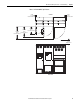
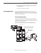
This section describes the main component sections of AFE Frame 10 and Frame
13 systems in a IP20 2500 MCC Style enclosure.
Frame 10
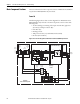
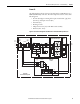
The following figure shows a basic one-line diagram for an AFE Frame 10 in a
IP20 2500 MCC Style enclosure. The main component sections consist of the
following items:
• AC Line Switchgear consisting of the input circuit breaker (Q0), fuses
(F1.1-F1.3), and input contactor (K1)
• LCL Filter (L1)
• Precharge Circuit
• AFE power structure (U1) with AFE control assembly
• DC fuses (F2.1 and F2.2)
Figure 6 - Basic One-line Diagram for an AFE Frame 10 in IP20 2500 MCC Style Enclosure
DC Bus
Output
L1
3 Phase
AC Input
L2
L3
PowerFlex
Active Front End System
Precharge
Circuit
R6.1
R6.2
+
-
AC Line Switchgear LCL Filter (L1) AFE
Power Structure (U1)
DC
Fuses
U2
V2
W2
C1
C2
C3
C4
C5
C6
U1
U1
V1
W1
U
DC+
DC-
V
F2.1
F2.2
W
PE
PE
Input
Contactor
K1
Fuses
F1.1-F1.3
Input
Breaker
Q0
Precharge
Contactor
Precharge
Fuses
F5
K6