
Owner manual

Rockwell Automation Publication 20Y-UM001E-EN-P - July 2014 151
Appendix C
Application Notes
Sizing Guidelines
Use the following guidelines to properly size the AFE.
Basic Procedure to Size the AFE
1. Sum the DC Input current rating of the connected drives.
See the respective drive documentation specifications, or Drives in
Common Bus Configurations, publication DRIVES-AT002.
2. Multiply the total DC current by 0.9.
This compensates for the boosted DC bus voltage that is provided by the
AFE.
3. Select the AFE with the DC current rating that meets or exceeds the value
calculated in step 2.
Examples:
• Normal Duty ND, 110%, 1 minute
• Heavy Duty HD, 150%, 1 minute
Topic Page
Sizing Guidelines
151
Voltage Boost
153
Paralleling AFEs
154
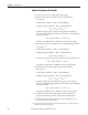
DC Input Rating of Connected Drives AFE
DC
Voltage
ND
Power
ND
Currents
ND Current
Sum x 0.9
ND Cont. DC
Output Amps
AC Input
Voltage
650V 5 x 60 HP
1 x 30 HP
5 x 84.5 = 422.5 A
1 x 85.8 A
457.5A 520A 480V
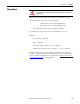
DC Input Rating of Connected Drives AFE
DC
Voltage
HD
Power
HD
Currents
HD Current
Sum x 0.9
HD Cont. DC
Output Amps
AC Input
Voltage
650V 5 x 60 HP
1 x 30 HP
5 x 84.5 = 422.5 A
1 x 55.7 = 55.7A
430.4A 435A 480V