
Owner manual


Rockwell Automation Publication 20Y-UM001E-EN-P - July 2014 141
Supplemental Information Appendix A
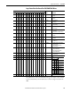
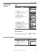
Logic Status Word for PowerFlex 700/700H/700S Drives
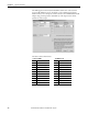
The AFE reference is the commanded bus voltage (for example, a value of 6000
represents 600.0V DC). The feedback value is the bus voltage measured in the
AFE.
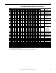
Logic Bits
1514131211109876543210Status Description
xReady 0 = Not Ready
1 = Ready
x Active 0 = Not Active
1 = Active
x Motoring 0 = Not Motoring
1 = Motoring
x Regenerating 0 = Not Regenerating
1 = Regenerating
x In Precharge 0 = Not In Precharge
1 = In Precharge
x Droop Active 0 = Not Droop Active for AFE
Paralleling
1 = Droop Active for AFE Paralleling
xAlarm0 = No Alarm
1 = Alarm
xFaulted0 = Not Faulted
1 = Faulted
x At Reference 0 = Not At Reference
1 = At Reference
x Mot CurLim 0 = Not Exceeding Current Limit in
Motoring Mode
1 = Exceeding Current Limit in
Motoring Mode
x Regen CurLim 0 = Not Exceeding Current Limit in
Regenerative Mode
1 = Exceeding Current Limit in
Regenerative Mode
x Cmd Delayed 0 = Condition False
1 = Condition True
x DCVoltRefID0
x DCVoltRefID1
x DCVoltRefID2
x Reserved
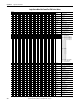
Bits
Description
14 13 12
000=DC Volt Ref
001=Analog In 1
010=Analog In 2
011=DPI Port 1
100=DPI Port 2
101=DPI Port 3
110=DPI Port 4
111=DPI Port 5