
Owner manual

140 Rockwell Automation Publication 20Y-UM001E-EN-P - July 2014
Appendix A Supplemental Information
DPI Communication
Configurations
This section contains information about using DPI communication with the
PowerFlex Active Front End.
Typical Programmable Controller Configurations
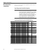
Logic Command Word for PowerFlex 700/700H/700S Drives
IMPORTANT
If programs are written that continuously write information to the AFE control,
take care to properly format the block transfer. If attribute 10 is selected for the
block transfer, values are written to only RAM and are not saved by the drive.
This is the preferred attribute for continuous transfers. If attribute 9 is selected,
each program scan completes a write to the drives nonvolatile memory
(EEPROM). Because the EEPROM accommodates only a fixed number of writes,
excessive continuous block transfers can quickly damage the EEPROM.
Therefore, do not assign attribute 9 to continuous block transfers. See the
individual communication adapter User Manual for additional details.
Logic Bits
1514131211109876543210Command Description
xStop 0 = Not Stop
1 = Normal Stop
xStart
(1)
0 = Not Start
1 = Start
x Reserved
xClear Fault
(2)
0 = Not Clear Fault
1 = Clear Fault
x Reserved
x Reserved
x Reserved
x Cmd LogicOut 0 = Network-controlled
Digital Output off
1 = Network-controlled
Digital Output on
x Reserved
x Reserved
x Reserved
x Reserved
x Reserved
x Reserved
x Reserved
x Reserved
(1) A Not Stop condition (logic bit 0 = 0, logic bit 8 = 0, and logic bit 9 = 0) must first be present before a 1 = Start condition starts the AFE.
(2) To perform this command, the value must switch from ‘0’ to ‘1’.