
Owner manual

124 Rockwell Automation Publication 20Y-UM001E-EN-P - July 2014
Chapter 5 Troubleshooting
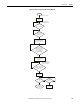
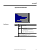
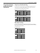
Figure 41 - AFE Fault Handling Sequence Troubleshooting Diagram
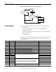
Technical Support
When contacting Technical Support, be prepared to provide this information:
• Order number
• Product catalog number and drives series number (if applicable)
• Product serial number
• Firmware revision level (verified using parameter 033 [Control SW Ver])
• Most recent fault code
• Your application
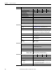
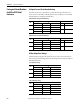
The data contained in the following parameters helps in initial troubleshooting
of a faulted drive. You can use the table below to record the data provided for
each listed parameter.
Stop the AFE
Fault active
Fault acknowledge
Fault acknowledge
Is Input Contactor
or circuit breaker
open?
Yes
No
No
Input Contactor or
circuit breaker open
Input Contactor or
circuit breaker closed
AFE Running
New Run
Command
Edge?
Yes
Parameter Name Description Recorded Parameter Data
104 Fault Frequency Captures and displays the AC line frequency at time of last fault.
105 Fault Total Curr Captures and displays the DC bus amps at time of last fault.
106 Fault Bus Volts Captures and displays the DC bus voltage at time of last fault.
107 Fault Temp Captures and displays the heatsink temperature at time of last fault.
108 Status 1 @ Fault Captures and displays [Cnvrtr Status 1] bit pattern at time of last fault.
109 Status 2 @ Fault Captures and displays [Cnvrtr Status 2] bit pattern at time of last fault.
110 Alarm 1 @ Fault Captures and displays [Cnvrtr Alarm 1] bit pattern at time of last fault.
111 Alarm 2 @ Fault Captures and displays [Cnvrtr Alarm 2] bit pattern at time of last fault.
124 Fault 1 Code Displays a code that represents the fault that tripped the AFE. The codes will appear in these
parameters in the order they occur ([Fault 1 Code] equals the most recent fault).
126 Fault 2 Code
128 Fault 3 Code
130 Fault 4 Code
125 Fault 1 Time Displays the time between initial unit power up and the occurrence of the associated trip
fault. Can be compared to [Power Up Marker] for the time from the most recent power up.
[Fault x Time] - [Power Up Marker] = Time difference to the most recent power up. A
negative value indicates fault occurred before most recent power up. A positive value
indicates fault occurred after most recent power up. Time stamp of the fault occurrence.
127 Fault 2 Time
129 Fault 3 Time
131 Fault 4 Time
137-140 Alarm Code 1-4 Displays a code that represents a converter alarm. The codes will appear in the order they
occur ([Alarm 1 Code] = the most recent alarm). A time stamp is not available with alarms.