
Owner manual

Rockwell Automation Publication 20Y-UM001E-EN-P - July 2014 109
Programming and Parameters Chapter 4
Inputs & Outputs File
File
Group
No. Parameter Name & Description Values
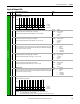
INPUTS & OUTPUTS
Analog Inputs
200 [Anlg In Config]
Selects the mode for the analog inputs.
201 [Analog In 1 Hi]
Sets the highest input value to the Analog Input 1 scaling block.
Parameter 200 [Anlg In Config] defines if this input will be -/+10V or 4-20 mA.
Default:
Min/Max:
Units:
10.000V
4.000/20.000 mA
-/+10.000V
0.001 mA
0.001V
202 [Analog In 1 Lo]
Sets the lowest input value to the Analog Input 1 scaling block.
Parameter 200 [Anlg In Config] defines if this input will be -/+10V or 4-20 mA.
Default:
Min/Max:
Units:
0.000V
4.000/20.000 mA
-/+10.000V
0.001 mA
0.001V
203 [Analog In 1 Loss]
Selects the AFE action when an analog signal loss is detected. Signal loss is defined as an analog signal
less than 1V or 2 mA. The signal loss event ends and normal operation resumes when the input signal
level is greater than or equal to 1.5V or 3 mA.
Default:
Options:
0
0
1
2
3
4
Disabled
Disabled
Fault
Hold Input
Set Input Lo
Set Input Hi
204 [Analog In 2 Hi]
Sets the highest input value to the Analog Input 2 scaling block.
Parameter 200 [Anlg In Config] defines if this input is -/+10V or 4-20 mA.
Default:
Min/Max:
Units:
10.000V
4.000/20.000 mA
-/+10.000V
0.001 mA
0.001V
205 [Analog In 2 Lo]
Sets the lowest input value to the Analog Input 2 scaling block.
Parameter 200 [Anlg In Config] defines if this input is -/+10V or 4-20 mA.
Default:
Min/Max:
Units:
0.000V
4.000/20.000 mA
-/+10.000V
0.001 mA
0.001V
206 [Analog In 2 Loss]
Selects the AFE action when an analog signal loss is detected. Signal loss is defined as an analog signal
less than 1V or 2 mA. The signal loss event ends and normal operation resumes when the input signal
level is greater than or equal to 1.5V or 3 mA.
Default:
Options:
0
0
1
2
3
4
Disabled
Disabled
Fault
Hold Input
Set Input Lo
Set Input Hi
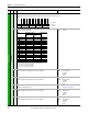
Analog Outputs
207 [Anlg Out Config]
Selects the mode for the analog outputs.
Important: Make sure the jumpers are in the correct position or the output will be wrong:
J3 = Analog Output 1; J4 = Analog Output 2
Position AB = Current; Position BC = Voltage 0-10V (default); Position CD = Voltage -/+10V
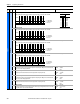
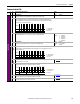
Bit
Definition
An2 (0 = V, 1 = mA)
An1 (0 = V, 1 = mA)
Default xxxxxxxxxxxxxx00
Bit 1514131211109 8 7 6 5 4 3 2 1 0
1 = Current
0 = Voltage
x = Reserved
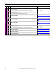
Bit
Definition
An2 (0 = V, 1 = mA)
An1 (0 = V, 1 = mA)
Default xxxxxxxxxxxxxx00
Bit 1514131211109 8 7 6 5 4 3 2 1 0
1 = Current
0 = Voltage
x = Reserved