
Owner manual

106 Rockwell Automation Publication 20Y-UM001E-EN-P - July 2014
Chapter 4 Programming and Parameters
UTILITY
Alarms
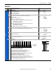
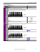
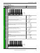
135 [Alarm Config]
Enables/disables alarm conditions that will initiate an AFE alarm.
• Bit 0 (Prechrg Actv) sets an alarm when the precharging is not completed.
• Bit 1 (DC UnderVolt) sets an alarm when the DC link voltage exceeded the limit.
• Bit 2 (Anlg In Loss) sets an alarm when the analog input is lost.
• Bit 3 (LineSyncFail) sets an alarm when the AC input line phase is missing.
• Bit 4 (HeatsinkOvTp) sets an alarm when the heatsink temperature is over temperature (90 °C).
• Bit 5 (LCL Fan Stop) sets an alarm when the LCL fan has been stopped.
• Bit 6 (DCRefLowLim) sets an alarm when the DC voltage reference is less than the limit in parameter 080 [DC Ref Lo Lmt].
• Bit 7 (DCRefHighLim) sets an alarm when the DC voltage reference exceeds the limit in parameter 081 [DC Ref Hi Lmt].
• Bit 8 (DCBusLoAlarm) sets an alarm when the DC voltage is less than the value set by parameter 078 [DC Bus Lo Alarm].
• Bit 9 (DCBusHiAlarm) sets an alarm when the DC voltage exceeds the value set by parameter 079 [DC Bus Hi Alarm].
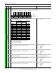
136 [Alarm Clear]
Resets all [Alarm 1…4 Code] parameters to ‘0’.
Default:
Options:
0
0
1
Ready
Ready
Clr Alarm Que
137
138
139
140
[Alarm 1 Code]
[Alarm 2 Code]
[Alarm 3 Code]
[Alarm 4 Code]
Displays a code that represents a converter alarm. The codes appear in the order they occur ([Alarm 1 Code] =
the most recent alarm). A time stamp is not available with alarms.
Default:
Min/Max:
Units:
Read Only
0/65535
None
File
Group
No. Parameter Name & Description Values
Bit
Definition
DCBusHiAlarm
DCBusLoAlarm
DCRefHighLim
DCRefLowLim
LCL Fan Stop
HeatsinkOvTp
LineSyncFail
Anlg In Loss
DC UnderVolt
Prechrg Actv
Default xxxxxx1111111111
Bit 1514131211109 8 7 6 5 4 3 2 1 0
1 = Enabled
0 = Disabled
x = Reserved