
Owner manual

Rockwell Automation Publication 20Y-UM001E-EN-P - July 2014 105
Programming and Parameters Chapter 4
UTILITY
Faults
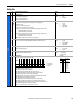
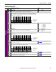
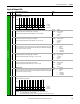
120 [Fault Config]
Enables/disables annunciation of the listed faults.
121 [Fault Clear]
Resets a fault and clears the fault queue.
0 (Ready) = A new value may be entered.
1 (Clear Faults) = A fault is reset.
2 (Clr Fault Que) = The fault queue is cleared.
Default:
Options:
0
0
1
2
Ready
Ready
Clear Faults
Clr Fault Que
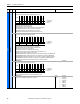
122 [Fault Clear Mode]
Enables/disables a fault reset (clear faults) attempt from any source. This does not apply to fault codes which
are cleared indirectly through other actions.
Default:
Options:
1
0
1
Enabled
Disabled
Enabled
123 [Power Up Marker]
Displays the elapsed hours since initial AFE power up. This value rolls over to ‘0’ after the AFE has been powered
on for more than the maximum value shown. For relevance to most recent power up, see parameters
128…131 [Fault x Time].
Default:
Min/Max:
Units:
Read Only
0.0000/429496.7295 Hr
0.0001 Hr
124
126
128
130
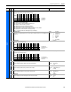
[Fault 1 Code]
[Fault 2 Code]
[Fault 3 Code]
[Fault 4 Code]
Displays a code that represents the fault that tripped the AFE. The codes appear in these parameters in the
order they occur (parameter 124 [Fault 1 Code] = the most recent fault).
Default:
Min/Max:
Units:
Read Only
0/65535
None
125
127
129
131
[Fault 1 Time]
[Fault 2 Time]
[Fault 3 Time]
[Fault 4 Time]
Displays the time between initial AFE power up and the occurrence of the associated trip fault. The time shown
by these parameters can be compared to parameter 123 [Power Up Marker] for the time from the most recent
power up. Therefore, [Fault x Time] - [Power Up Marker] = Time difference to the most recent power up. A
negative value indicates the fault occurred before the most recent power up. A positive value indicates the fault
occurred after the most recent power up.
Default:
Min/Max:
Units:
Read Only
0.0000/429496.7295 Hr
0.0001 Hr
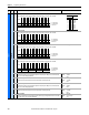
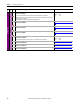
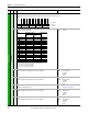
132 [Contact Off Cnfg]
Configures faults that will force the main contactor off in case of fault. This is only possible if the precharge
contactor is off or controlled over the network (Digital output selection) and the AFE is supplied by an external
24V DC power supply.
This provides an option to protect the AFE when the AFE is faulted, modulating is stopped, and the motoring
current can still flow through the IGBT diode.
133 [Cnvrtr OL Factor]
Sets the operating level for the AFE overload.
(AFE rated current) x (AFE OL Factor) = Operating Level
Default:
Min/Max:
Units:
1.00
0.50/1.50
None
File
Group
No. Parameter Name & Description Values
Bit
Definition
AutoResetLim
Overload
LineSyncFail
DC UnderVolt
Default xxxxxxxxxx000x0x
Bit 1514131211109 8 7 6 5 4 3 2 1 0
1 = Enabled
0 = Disabled
x = Reserved
32
32
Bit
Definition
All Fault
LCL OverTemp
HeatsinkOvTp
Overload
AC OverCurr
IGBTOverTemp
DC OverVolt
Auxiliary In
Default xxxxxx0000x000x0
Bit 1514131211109 8 7 6 5 4 3 2 1 0
1 = Enabled Contactor Off command from fault*
0 = Disabled Contactor Off command from fault
x = Reserved
* If enabled, the auto restart function will be disabled.