
Owner manual

Rockwell Automation Publication 20Y-UM001E-EN-P - July 2014 103
Programming and Parameters Chapter 4
UTILITY
Diagnostic
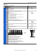
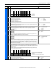
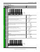
100 [Start Inhibits]
Displays the inputs presently preventing the AFE from starting.
• Bit 0 (Fault) is set when the AFE is faulted.
• Bit 1 (Type 2 Alarm) is set when the AFE has an alarm of type 2.
• Bit 2 (Enable) is set when the AFE is not enabled.
• Bit 3 (DC Bus Pchrg) is set when the AFE is in precharging.
• Bit 4 (Stop Assertd) is set when a stop command is asserted.
• Bit 5 (Params Reset) is set when parameter 091 [Reset To Defaults] is reset to defaults.
• Bit 6 (Startup Actv) is set when the AFE is in startup sequencing.
• Bits 9…13 indicate the AFE start is inhibited by the respective DPI port.
Read Only
101 [Last Stop Source]
Displays the source that initiated the most recent stop sequence. It will be cleared (set to zero) during the next
start sequence.
Default:
Options: 0
1-5
6
7
8
9
Read Only
Pwr Removed
DPI Port 1-5
Reserved
Digital In
Fault
Not Enabled
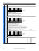
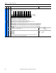
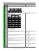
102 [Dig In Status]
Displays the status of the digital inputs.
Read Only
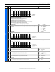
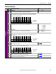
103 [Dig Out Status]
Displays the status of the digital outputs.
Read Only
104 [Fault Frequency]
Captures and displays the AC line frequency at the time of the last fault.
Default:
Min/Max:
Units:
Read Only
-63.0/63.0 Hz
0.1 Hz
105 [Fault Total Curr]
Captures and displays the DC bus amps at the time of the last fault.
Default:
Min/Max:
Units:
Read Only
0.0/[Rated Amps] x 2
0.1 Amps
106 [Fault Bus Volts]
Captures and displays the DC bus voltage at the time of the last fault.
Default:
Min/Max:
Units:
Read Only
0/Max Bus Volts
1V DC
107 [Fault Temp]
Captures and displays the heatsink temperature at the time of the last fault.
Default:
Min/Max:
Units:
Read Only
0/200 °C
1 °C
File
Group
No. Parameter Name & Description Values
Bit
Definition
DPI Port 5
DPI Port 4
DPI Port 3
DPI Port 2
DPI Port 1
Startup Actv
Params Reset
Stop Assertd
DC Bus Pchrg
Enable
Type 2 Alarm
Fault
Default xx00000xx0000000
Bit 1514131211109 8 7 6 5 4 3 2 1 0
1 = Inhibit True
0 = Inhibit False
x = Reserved
Bit
Definition
Digital In6
Digital In5
Digital In4
Digital In3
Digital In2
Digital In1
Default xxxxxxxxxx000000
Bit 1514131211109 8 7 6 5 4 3 2 1 0
1 = Input Present
0 = Input Not Present
x = Reserved
Bit
Definition
DigitalOut 3
DigitalOut 2
DigitalOut 1
Default xxxxxxxxxxxxx000
Bit 1514131211109 8 7 6 5 4 3 2 1 0
1 = Output Present
0 = Output Not Present
x = Reserved
32