
Owner manual

102 Rockwell Automation Publication 20Y-UM001E-EN-P - July 2014
Chapter 4 Programming and Parameters
UTILITY
Diagnostics
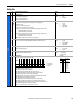
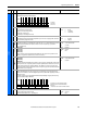
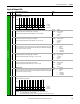
096 [Cnvrtr Status 2]
Displays the present operating condition of the AFE and active source.
• Bit 0 (Ready) indicates all inhibits are cleared.
• Bit 1 (Active) indicates the AFE is modulating.
• Bit 2 (ModIndexLim) indicates the AFE reached the modulation index limitation.
• Bit 8 (AutoRst Ctdn) indicates the auto restart timer is counting down.
• Bit 9 (AutoRst Act) indicates the auto restart function is activated.
• Bit 13 (DPI at 500k) indicates DPI communication with 500k of baud rate.
Read Only
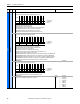
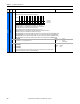
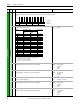
097 [Cnvrtr Alarm 1]
Displays alarm conditions that presently exist in the unit.
• Bit 0 (Prechrg Actv) indicates that precharging is not completed.
• Bit 1 (DC UnderVolt) indicates the DC link voltage exceeded the limit.
• Bit 2 (Anlg In Loss) indicates the analog input loss.
• Bit 3 (LineSync Fail) indicates the AC input line phase is missing.
• Bit 4 (HeatsinkOv Tp) indicates the heatsink temperature is over temperature (90 °C).
• Bit 5 (LCL Fan Stop) indicates the LCL fan has been stopped.
• Bit 6 (DCRefLowLim) indicates the DC voltage reference is less than the limit in parameter 080 [DC Ref Lo Lmt].
• Bit 7 (DCRefHighLim) indicates the DC voltage reference exceeds the limit in parameter 081 [DC Ref Hi Lmt].
• Bit 8 (DCBusLo Alarm) indicates the DC voltage is less than the value set by parameter 078 [DC Bus Lo Alarm].
• Bit 9 (DCBusHi Alarm) indicates the DC voltage exceeds the value set by parameter 079 [DC Bus Hi Alarm].
• Bit 10 (Overload) indicates that parameter 003 [Total Current] exceeds the rated current.
Read Only
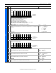
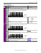
098 [Cnvrtr Alarm 2]
Displays alarm conditions that presently exist in the unit.
• Bit 0 (DigInConflict) indicates there is a conflict with the digital input settings.
• Bit 1 (Contact Fdbk) indicates there is no feedback from the main contact.
Read Only
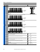
099 [DC Ref Source]
Displays the source of the DC bus voltage reference to the unit.
Default:
Options: 0
1
2
3
4
5
6
7
Read Only
DC Volt Ref
Analog In1
Analog In2
DPI Port 1
DPI Port 2
DPI Port 3
DPI Port 4
DPI Port 5
File
Group
No. Parameter Name & Description Values
Bit
Definition
DPI at 500k
AutoRst Act
AutoRst Ctdn
ModIndexLim
Active
Ready
Default xx0xxx00xxxxx000
Bit 1514131211109 8 7 6 5 4 3 2 1 0
1 = Condition True
0 = Condition False
x = Reserved
Bit
Definition
Overload
DCBusHiAlarm
DCBusLoAlarm
DCRefHighLim
DCRefLowLim
LCL Fan Stop
HeatsinkOvTp
LineSyncFail
Anlg In Loss
DC UnderVolt
Prechrg Actv
Default xxxxx11111111111
Bit 1514131211109 8 7 6 5 4 3 2 1 0
1 = Condition True
0 = Condition False
x = Reserved
Bit
Definition
Contact Fdbk
DigInConflict
Default xxxxxxxxxxxxxx00
Bit 1514131211109 8 7 6 5 4 3 2 1 0
1 = Condition True
0 = Condition False
x = Reserved