
Owner manual

Rockwell Automation Publication 20Y-UM001E-EN-P - July 2014 101
Programming and Parameters Chapter 4
Utility File
File
Group
No. Parameter Name & Description Values
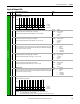
UTILITY
Converter Memory
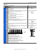
090 [Param Access Lvl]
Selects the parameter display level.
0 (Basic) = Reduced parameter set.
1 (Advanced) = Full parameter set.
Default:
Options:
0
0
1
Basic
Basic
Advanced
091 [Reset to Defaults]
Resets parameters to factory defaults except parameters 093 [Language] and
090 [Param Access Lvl].
0 (Ready) = A new value may be entered.
1 (Factory) = Resets parameters to factory defaults.
2 (Low Voltage) = Resets parameters to factory defaults and configures parameters for a:
• 400/480V AFE unit for 400V operation.
• 600/690V AFE unit for 600V operation.
3 (High Voltage) = Resets parameters to factory defaults and configures parameters for a:
• 400/480V AFE unit for 480V operation.
• 600/690V AFE unit for 690V operation.
NOTE: The DC bus voltage must be present to set the voltage class.
Default:
Options:
0
0
1
2
3
Ready
Ready
Factory
Low Voltage
High Voltage
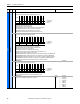
092 [Reset Meters]
Resets these selected meters (Motoring MWh, Regen MWh, and Elapsed Time) to zero.
Default:
Options:
0
0
1
2
3
Ready
Ready
Motoring MWh
Regen MWh
Elapsed Time
093 [Language]
Limited to English language only.
Default:
Options:
0
0
1
Not Selected
Not Selected
English
094 [Voltage Class]
Displays the last ‘Reset To Defaults’ operation.
Default:
Options:
Read Only
0 = Low Voltage
1 = High Voltage
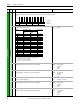
Diagnostics
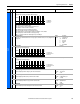
095 [Cnvrtr Status 1]
Displays the present operating condition of the AFE.
• Bit 0 (Ready) indicates all inhibits are cleared.
• Bit 1 (Active) indicates the AFE is modulating.
• Bit 2 (Motoring) indicates the AFE is running in motoring mode.
• Bit 3 (Regenerating) indicates the AFE is regenerating power to the AC line.
• Bit 4 (In Precharge) indicates the AFE is in precharging status.
• Bit 5 (Droop Active) indicates that the droop function for AFE paralleling is activated.
• Bit 6 (Alarm) indicates the AFE has detected an alarm.
• Bit 7 (Faulted) indicates the AFE has detected a fault.
• Bit 8 (At Reference) indicates the DC bus voltage is at the command value.
• Bit 9 (Mot CurLim) indicates the AFE exceeds the current limit in motoring mode.
• Bit 10 (Regen CurLim) indicates the AFE exceeds the current limit in regenerative mode.
• Bit 11 (Cmd Delayed) indicates pending start command.
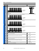
• Bits 12…14 indicate the DC bus voltage reference selection.
Read Only
Bit
Definition
DCVoltRefD2
DCVoltRefD1
DCVoltRefD0
Cmd Delayed
Regen CurLim
Mot CurLim
At Reference
Faulted
Alarm
Droop Active
In Precharge
Regenerating
Motoring
Active
Ready
Default x000000000000000
Bit 1514131211109 8 7 6 5 4 3 2 1 0
1 = Condition True
0 = Condition False
x = Reserved
Bits Description
14 13 12
0
0
0
0
1
1
1
1
0
0
1
1
0
0
1
1
0
1
0
1
0
1
0
1
DC Volt Ref
Analog In1
Analog In2
DPI Port 1
DPI Port 2
DPI Port 3
DPI Port 4
DPI Port 5