
Owner manual

90 Rockwell Automation Publication PFLEX-IN029B-EN-P - August 2014
Chapter 3 PowerFlex 700H and 700S Drives - Frame 11 Procedures
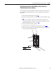
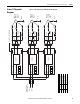
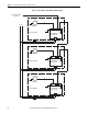
Figure 7 - Frame 11 DC Fan System Wiring Schematic Diagram
3
To ASIC Circuit Board X11
(Fan Control)
4
Main DC Fan
W Phase Fan Module
DC- DC+
Isolated 48 VDC Power
Supply Circuit Board
X81 X8 X3
X82
X2
4
Main DC Fan
V Phase Fan Module
Isolated 48 VDC Power
Supply Circuit Board
X81 X8 X3
X82
X2
4
Main DC Fan
U Phase Fan Module
Isolated 48 VDC Power
Supply Circuit Board
X81 X8 X3
X82
X2