
Owner manual

Rockwell Automation Publication PFLEX-IN029B-EN-P - August 2014 83
PowerFlex 700H and 700S Drives - Frame 10 Procedures Chapter 2
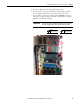
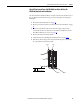
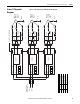
4. Remove the ASIC circuit board assembly from the drive:
• For earlier drives, remove the four M4 x 8 mm hexalobular screws that
secure the ASIC assembly cover to the drive and remove the cover.
• For newer drives, remove the two M3 x 5 mm POZIDRIV screws that
secure the cooling fan assembly to the ASIC assembly and rotate the fan
assembly out of the ASIC assembly.
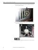
IMPORTANT
After removing the fan assembly from the ASIC board assembly, the
fan power cable will still be connected to the ASIC circuit board.
PZ2
3.0 N•m (27 lb•in)
4
T20
1.65 N
•m (14.6 lb•in)