
Owner manual


Rockwell Automation Publication PFLEX-IN029B-EN-P - August 2014 73
PowerFlex 700H and 700S Drives - Frame 10 Procedures Chapter 2
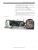
7. Install the new DC fan assemblies in the reverse order of removal as
instructed in step 4
, using the connection locations identified in Tabl e 1 .
8. Remove the backing from the drive modification label and attach the label,
in a clearly visible location, to the front of the drive.
9. Write “DC fan retrofit” and the installation date on the label.
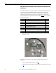
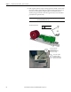
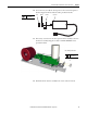
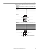
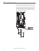
Table 1 - DC Fan Inverter Connections
Item Description
1 DC supply wire to connector X2
2 Fan control wire to connector X8
3 Fan control FB wire/jumper to connector X3
4 Fan supply wire to DC fan extension wire connector