
Owner manual

Rockwell Automation Publication PFLEX-IN029B-EN-P - August 2014 59
PowerFlex 700H and 700S Drives - Frame 10 Procedures Chapter 2
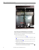
Frame 10 Fan System
Replacement Procedures
Replacement procedures for these frame 10 fan system parts are included in this
chapter.
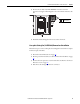
Remove Power from the Drive
1. Turn off and lock out input power.
2. Wa i t f i ve m i n ut e s .
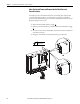
3. Check the DC bus voltage at the Power Terminal Block by measuring
between the +DC and -DC terminals, between the +DC terminal and the
chassis, and between the -DC terminal and the chassis. The voltage must
be zero for all three measurements.
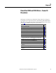
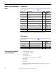
Cat. No. Part Description Page
20-FR10844 Output transformer assembly for AC fan inverter (left side)
(1)
(1) This assembly does not include the main fan inverter circuit board.
67
20-FR10845 Output transformer assembly for AC fan inverter (right side)
(1)
67
20-VB00299 Main AC fan inverter circuit board 67
SK-H1-DCFANBD1 Main DC fan power supply circuit board 69
SK-H1-DCFANRETROFIT-F10 AC to DC fan system retrofit kit 70
SK-H1-FANCAP-F1012 Main AC fan capacitor (7 μF) Kit 74
20-PP01080 230 W main AC fan assembly 78
SK-Y1-DCFAN1 Main DC fan assembly 78
20-PP01096 60 mm internal fan for ASIC board 82
20-PP20202 Fuse for fan system 85
20-PP20300 Fuse holder for main fan system fuses 85
ATTENTION: To avoid an electric shock hazard, verify that the voltage on the bus
capacitors has discharged completely before servicing. Check the DC bus voltage
at the Power Terminal Block by measuring between the +DC and -DC terminals,
between the +DC terminal and the chassis, and between the -DC terminal and
the chassis. The voltage must be zero for all three measurements.
Remove power before making or breaking cable connections. When you remove or
insert a cable connector with power applied, an electrical arc may occur. An
electrical arc can cause personal injury or property damage by:
• sending an erroneous signal to your system’s field devices, causing unintended
machine motion
• causing an explosion in a hazardous environment
Electrical arcing causes excessive wear to contacts on both the module and its
mating connector. Worn contacts may create electrical resistance.
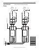
L1 L2 L3
O
I