
Owner manual

Rockwell Automation Publication PFLEX-IN029B-EN-P - August 2014 55
Chapter 2
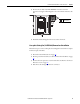
PowerFlex 700H and 700S Drives - Frame 10
Procedures
This chapter contains spare part information and procedures for testing and
replacing fan system components for frame 10 PowerFlex 700H and PowerFlex
700S drives. See Appendix A PowerFlex 700H and 700S Diagnostic Procedures
on page 255
for additional component test procedures.
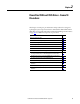
Topic Page
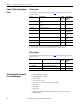
Frame 10 Fan System Spare Parts 56
Tools Needed for Frame 10 Fan System Repairs 56
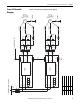
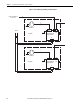
Frame 10 Schematic Diagrams 57
Frame 10 Fan System Replacement Procedures 59
Remove Power from the Drive 59
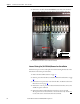
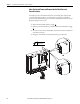
Move the Control Frame and Remove the Air Flow Plate and Protective Covers 60
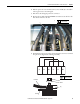
Remove the Main AC or DC Fan Power Supply Assemblies 63
Main AC Fan Inverter Circuit Board (20-VB00299) and AC Fan Output Transformer
Assembly [20-FR10844 (Left) or 20-FR10845 (Right)] Removal and Installation
67
Main DC Fan Power Supply System (SK-H1-DCFANBD1) Removal and Installation 69
AC to DC Fan System Retrofit Kit (SK-H1-DCFANRETROFIT-F10) 70
Main AC Fan Inverter Capacitor (SK-H1-FANCAP-F1012) Removal and Installation 74
Main AC Fan (20-PP01080) and Main DC Fan (SK-Y1-DCFAN1) Assembly Removal and
Installation
78
ASIC Circuit Board Assembly Cooling Fan (20-PP01096) Removal and Installation 82
AC or DC Fan System Fuses (20-PP20202) and Fuse Holder (20-PP20300) Removal and
Installation
85