
Owner manual

Rockwell Automation Publication PFLEX-IN029B-EN-P - August 2014 53
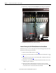
PowerFlex 700H and 700S Drives - Frame 9 Procedures Chapter 1
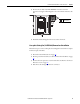
6. Push the power wires on terminals U/T1, V/T2, and W/T3 to the side in
order to gain access to the stirring fan.
7. Disconnect the stirring fan power wire connector.
8. Remove the two M4 x 8 mm POZIDRIV screws that secure the fan to the
drive frame and remove the fan.
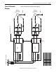
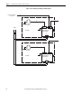
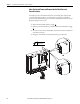
9. Install the fan in the reverse order of removal. Refer to the motor terminal
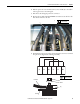
wire placement diagrams below during reassembly.
7
8
PZ2
3.0 N•m (27 lb•in)
Lug
Hex Nut
Washer
Bus Bar
Power Wire
U1 U2
V1
V2
W1 W2
13 mm
20.0 N
•m (177 lb•in)