
Owner manual

46 Rockwell Automation Publication PFLEX-IN029B-EN-P - August 2014
Chapter 1 PowerFlex 700H and 700S Drives - Frame 9 Procedures
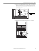
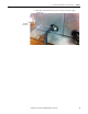
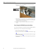
8. Using the appropriate table below, measure the resistance between the fan
supply wires.
AC Fan: If the measurements are not similar to those in this table, replace
the AC fan.
DC Fan: If the measurements are not similar to those in this table, replace
the DC fan.
Connection wires Resistance ±5%
Black-Brown 62 Ω
Brown-Blue 36 Ω
Blue-Black 27 Ω
Green-chassis 0 Ω
Connection wires Resistance ±5%
Red-Blue ∞ Ω
Red-White ∞ Ω
White-Yellow ∞ Ω
Blue-White ∞ Ω
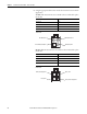
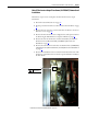
Blue (Motor) Pin 4
Green/Yellow (Ground) Pin 1
Brown (Motor) Pin 3
Black (Motor) Pin 2
AC Fan Pinouts
White (Tach Output) Pin 3
Red (+) Pin 1
Blue (-) Pin 4
Yellow (Control Output) Pin 2
DC Fan Pinouts