
Owner manual

Rockwell Automation Publication PFLEX-IN029B-EN-P - August 2014 43
PowerFlex 700H and 700S Drives - Frame 9 Procedures Chapter 1
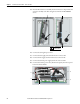
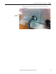
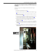
21. Secure the fan inverter cover to the drive using the M4 x 8 mm
POZIDRIV screw.
22. Install the lower protective cover in the reverse order of removal. See
Remove the Lower Protective Cover on page 24
.
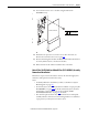
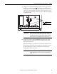
23. Remove the backing from the drive modification label and attach the label,
in a clearly visible location, to the front of the drive.
24. Write “DC fan retrofit” and the installation date on the label.
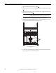
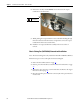
Main AC Fan (20-PP01080) and Main DC Fan (SK-Y1-DCFAN1) Assembly
Removal and Installation
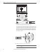
Follow these steps to measure the resistance between the main fan supply wires
and remove and replace the main fan, if necessary.
Notes:
• To identify which fan is installed in your drive, see Fan Inverter System
Block Diagrams on page 257
.
• For AC fan systems, the sheet metal bracket is available as a spare part (SK-
H1-FR9BRKT). See page 288
for details. For DC fan systems, the sheet
metal bracket is only available as part of the retrofit kit (SK-H1-
DCFANRETROFIT-F9). See page 289
for details.
• The main fan replacement kit only contains the fan motor and impeller
assembly. Therefore, if the sheet metal mounting bracket is not available as
a spare part for your fan system, it must be reused.
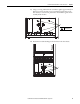
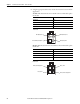
1 2 3 4
ON
X6
X1
X4
X5
X7
S1
X2 X8
PZ2
1.3 N
•m (11.5 lb•in)
Series A Cover Shown