
Owner manual

28 Rockwell Automation Publication PFLEX-IN029B-EN-P - August 2014
Chapter 1 PowerFlex 700H and 700S Drives - Frame 9 Procedures
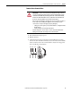
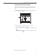
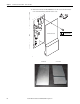
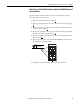
8. Remove the two M5 x 10 mm Phillips head screws that secure the fan
capacitor, fuse holder, and cooling fan bracket to the drive frame and lift
the bracket out of the drive.
Note that the fan capacitor is still connected to the drive circuitry.
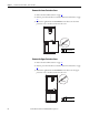
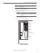
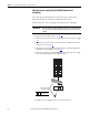
9. Disconnect the fan capacitor wires from the connectors labeled ‘Blue’ and
‘Brown’.
1
2
3
4
ON
X6
X1
X4
X5
X7
S1
X2 X8
9
8
P2
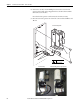
4.0 N
•m (35 lb•in)
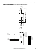
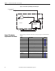
Series A Assembly Shown
Series A Assembly Series B Assembly (Note the Larger Capacitor)