
Owner manual

Rockwell Automation Publication PFLEX-IN029B-EN-P - August 2014 275
PowerFlex 700H and 700S Diagnostic Procedures Appendix A
AC Fan System Test
Complete the following steps to test the AC fan system.
1. Connect an external 500V DC source, through two fuses, similar to those
on the drive power structure (Ferraz ATQ8), to connector X2 (+DC to
pin 3 and –DC to pin 1) on the fan inverter circuit board.
2. Connect X3 and X8 to a test fixture that incorporates 2 switches and
appropriate interconnection wires. SW1 between X3, pins 2 - 4 and SW2
between X8, pins 3 - 5.
3. Connect the fan inverter circuit board (terminals X4 and X5) to the fan
power conditioning hardware, 7 μF capacitor and AC fan.
4. Carefully apply a 500V DC source.
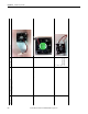
5. Evaluate the AC fan inverter circuit board in each of the switch
configurations and view the LED status and fan rotation against the states
listed in Ta b l e 5
. If the LED status and fan rotation is NOT consistent
with the table, the circuit board is not functioning and must be replaced. If
the LED status and fan rotation agrees with the table, the circuit board
should be ok and can be used or further evaluated.
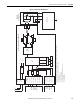
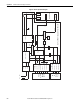
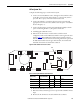
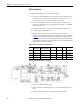
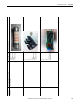
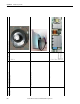
Figure 41 - LEDs and Fan Connections Locations
Table 5 - AC Fan System LED Status and Switch States
6. Remove the 500V DC source power.
7. Wait a few minutes and verify power is not present with a DVM at the fuse
input.
8. Remove the AC fan inverter circuit board from the test fixture.
X3
X8
X2
X4 X5
LEDs
SW1
(Next Fan Inv)
SW2
(Fan Control Enable)
Red LED Green LED Comment
Open Open ON ON Faulted
Open Closed ON ON Faulted
Closed Open OFF ON Idle
Closed Closed OFF Flashing Running