
Owner manual

272 Rockwell Automation Publication PFLEX-IN029B-EN-P - August 2014
Appendix A PowerFlex 700H and 700S Diagnostic Procedures
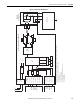
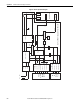
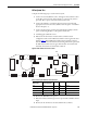
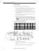
Figure 40 - DC Fan System Block Diagram
DC Fan Power Supply Circuit Board
ASIC
Circuit
Board
(X11)
X8
of
Next
Fan
X8
X3
X2
1 - DC+
3 - DC-
1 - Fan PWM
2 - Iso +18V
3 - Fan Control
4 - Fan Alarm Fr9
5 - DC- Ref
6 - Fan Alarm Fr8
7 - Fan Alarm Fr10
OPTO
OPTO
OPTO
1 - Next Fan PWM
2 - Iso +18V*
3 - Next Fan Control
4 - Next Fan Alarm*
dc/dc Converter
Fault Detect
Driver
X81 Blue
X81 Red
DC+DC-
Isolation
PWM Contoller
DC-
+18V
Ifdbk
Temp
OPTO
+
_
X81 Yellow
X81 White
Rotate
48V DC Fan
Vfdbk
Control