
Owner manual

Rockwell Automation Publication PFLEX-IN029B-EN-P - August 2014 271
PowerFlex 700H and 700S Diagnostic Procedures Appendix A
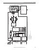
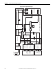
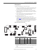
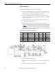
Figure 39 - AC Fan System Block Diagram
AC Fan Inverter Circuit Board
ASIC
Circuit
Board
(X11)
X8
of
Next
Fan
X8
X3
X2
1 - DC+
3 - DC-
1 - Fan PWM
2 - Iso +18V
3 - Fan Control
4 - Fan Alarm Fr9
5 - DC- Ref
6 - Fan Alarm Fr8
7 - Fan Alarm Fr10
OPTO
OPTO
OPTO
1 - Next Fan PWM
2 - Iso +18V*
3 - Next Fan Control
4 - Next Fan Alarm*
* X3 is also used as the loopback pin set. When used as a loopback, a jumper connects Pins 2 and 4.
For PowerFlex 700H/700S drives, the jumper occurs on:
Fr. 9 - First board
Fr. 10/12 - Second board
Fr. 11/13/14 - Third board
For the PowerFlex 700AFE, the jumper occurs on:
Fr. 10 - First board
Fr. 13 - Third board
SMPS
+18V
-DC
+5V
-18V
µP
Temp
Bov
Ioc
I
2
t
Fault Detect
NTC DC
FDBK
I
SENSE
Gate
Driver
Board
UH
VH
UL
VL
DC+
DC-
Output
Transformer
AC Fan
Blue
Black
Brown
X4
Blue
X5
Black
7 µF
Σ
Green
DC+DC-
Blue
Brown
2.2 µF2.2 µF
10 MΩ10 MΩ