
Owner manual

Rockwell Automation Publication PFLEX-IN029B-EN-P - August 2014 269
PowerFlex 700H and 700S Diagnostic Procedures Appendix A
• For frame 11 drives, Main AC Fan Inverter Circuit Board (20-VB00299)
and AC Output Transformer Assembly (20-FR10845) Removal and
Installation on page 99
or
Main DC Fan Power Supply Circuit Board (SK-H1-DCFANBD1)
Removal and Installation on page 101
• For frame 13 and 14 drives, Main AC Fan Inverter Circuit Board (20-
VB00299) Removal and Installation (Inverter Only) on page 151
or
Main DC Fan Power Supply Circuit Board (SK-H1-DCFANBD1)
Removal and Installation (Inverter Only) on page 153
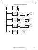
AC Fan System LEDs
Each AC fan inverter has a red and green diagnostic LED. The diagnostic LEDs
can be used to determine whether the AC fan inverter board must be replaced.
These LEDs can only be viewed when the AC fan inverter board is removed from
the drive and energized with an external power supply and control circuitry.
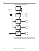
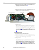
DC Fan System LEDs
Each DC fan inverter has a red, yellow and green diagnostic LED. The diagnostic
LEDs can be used to determine whether the DC fan inverter board must be
replaced. These LEDs can only be viewed when the DC fan inverter board is
removed from the drive and energized with an external power supply and control
circuitry.
ATTENTION: The inverter LEDs are only operational when the drive is
energized, and only visible with the protective covers removed from the power
structure. Servicing energized equipment can be hazardous. Severe injury or
death can result from electrical shock, burn or unintended actuation of
controlled equipment. Follow Safety related practices of NFPA 70E, ELECTRICAL
SAFETY FOR EMPLOYEE WORKPLACES. DO NOT work alone on energized
equipment!
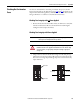
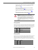
Red LED Green LED Status
Off On Inverter is idle (stopped)
Off Flashing Inverter is running
On On Inverter is faulted - replace the main fan inverter assembly
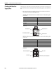
Component LED Color Description
H6 Green Power On
H8 Yellow Fan control enabled
H9 Red Minimum fan rotation speed has not been reached