
Owner manual

268 Rockwell Automation Publication PFLEX-IN029B-EN-P - August 2014
Appendix A PowerFlex 700H and 700S Diagnostic Procedures
2. Energize the drive.
3. If all three fan inverter circuit boards fault, then replace the U phase fan
inverter circuit board. For AC fan systems, see Main AC Fan Inverter
Circuit Board (20-VB00299) and AC Output Transformer Assembly (20-
FR10845) Removal and Installation on page 99
. For DC fan systems, see
Main DC Fan Power Supply Circuit Board (SK-H1-DCFANBD1)
Removal and Installation on page 101
.
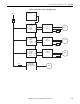
Frames 13 and 14 PowerFlex 700H and 700S Drives
For more details, see:
• Frame 13 AFE Schematic Diagrams on page 125
• Frame 14 System Diagrams on page 182
Additional procedures will be added to future revisions of this publication as they
become available. Enter ‘PFLEX-IN029’ in the Search field on the Rockwell
Automation Literature Library at:
http:/www.rockwellautomation.com/literature/
.
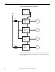
Frames 10 and 13 PowerFlex 700AFE
For more details, see:
• Frame 10 AFE Fan System Schematic Diagrams on page 189
• Frame 13 AFE Schematic Diagrams on page 240
Additional procedures will be added to future revisions of this publication as they
become available. Enter ‘PFLEX-IN029’ in the Search field on the Rockwell
Automation Literature Library at:
http:/www.rockwellautomation.com/literature/
.
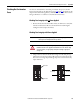
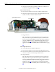
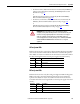
Checking the Main AC Fan
Inverter Circuit Board
Diagnostic LEDs
PowerFlex 700H and 700S drives have one or more AC or DC fan inverters. To
troubleshoot the fan inverter circuit board, you must remove it from the drive.
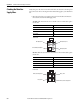
Remove the main AC or DC fan inverter circuit board from the drive. See:
• For frame 9 drives, Main AC Fan Inverter Circuit Board Assembly (20-
VB00299) Removal and Installation on page 33
or
Main DC Fan Power Supply Circuit Board (SK-H1-DCFANBD1)
Removal and Installation on page 36
• For frame 10 and 12 drives, Main AC Fan Inverter Circuit Board (20-
VB00299) and AC Fan Output Transformer Assembly [20-FR10844
(Left) or 20-FR10845 (Right)] Removal and Installation on page 67
or
Main DC Fan Power Supply System (SK-H1-DCFANBD1) Removal and
Installation on page 69