
Owner manual

264 Rockwell Automation Publication PFLEX-IN029B-EN-P - August 2014
Appendix A PowerFlex 700H and 700S Diagnostic Procedures
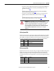
Checking the Main Fan
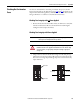
Supply Wires
Verify that power has been removed from the drive. To disconnect the fan power
wire connection, refer to the chapter in this manual that apply to your drive frame
size.
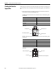
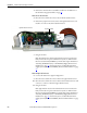
• Disconnect the fan power supply connector from the drive and measure
the resistance between the fan supply wires.
AC Fan: If the measurements are not similar to those in this table, replace
the AC fan.
DC Fan: If the measurements are not similar to those in this table, replace
the DC fan.
Connection wires Resistance ±5%
Black-Brown 62 Ω
Brown-Blue 36 Ω
Blue-Black 27 Ω
Green-chassis 0 Ω
Connection wires Resistance ±5%
Red-Blue ∞ Ω
Red-White ∞ Ω
White-Yellow ∞ Ω
Blue-White ∞ Ω
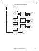
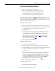
Blue (Motor) Pin 4
Green/Yellow (Ground) Pin 1
Brown (Motor) Pin 3
Black (Motor) Pin 2
AC Fan Pinouts
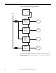
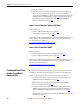
White (Tach Output) Pin 3
Red (+) Pin 1
Blue (-) Pin 4
Yellow (Control Output) Pin 2
DC Fan Pinouts