
Owner manual

Rockwell Automation Publication PFLEX-IN029B-EN-P - August 2014 249
PowerFlex 700AFE Drive - Frame 13 Procedures Chapter 8
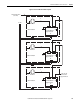
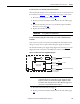
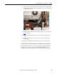
8. Connect the new cable to X51 on the LCL filter fan power supply and X3
on the AFE power module. The extra flying lead connects to the –DC bus
terminal as shown here.
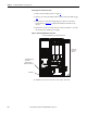
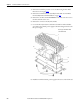
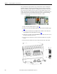
9. Install the new LCL filter fan power supply using the screws provided. See
step 6
for details.
10. Connect the X51 and X53 connectors to the fan power supply circuit
board.
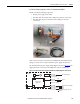
11. Insert the X1 fan cable connector into the receptacle on the fan sheet
metal housing.
12. If necessary, install the LCL filter fan in the reverse order of removal.
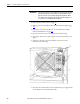
LCL Filter Fan DC Power Supply Circuit Board (SK-H1-DCFANBD1) Removal and Installation
If the LCL filter already has a new fan power supply kit (SK-Y1-DCPS2-F13)
installed, the DC fan power supply board (SK-H1-DCFANBD1) can be
installed as a replacement part in the newer version DC power supply system.