
Owner manual

Rockwell Automation Publication PFLEX-IN029B-EN-P - August 2014 231
PowerFlex 700AFE Drive - Frame 10 Procedures Chapter 7
1. Review the General Precautions on page 17.
2. Remove power from the AFE. See Remove Power from the AFE on page
192
.
3. Remove the LCL filter fan assembly from the AFE. See LCL Filter Fan
Assembly Removal and Installation on page 229
.
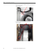
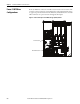
4. Disconnect the X1 connector from the sheet metal housing.
5. Measure the resistance between the fan supply wires.
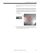
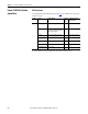
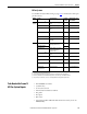
DC Fan: If the measurements are not similar to those in this table, replace
the DC fan.
Connection wires Resistance ±5%
Red-Blue ∞ Ω
Red-White ∞ Ω
White-Yellow ∞ Ω
Blue-White ∞ Ω
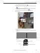
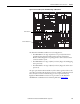
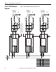
4Image for SK-Y1-DCPS2-F10
White (Tach Output) Pin 3
Red (+) Pin 1
Blue (-) Pin 4
Yellow (Control Output) Pin 2
DC Fan Pinouts