
Owner manual

206 Rockwell Automation Publication PFLEX-IN029B-EN-P - August 2014
Chapter 7 PowerFlex 700AFE Drive - Frame 10 Procedures
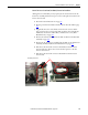
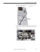
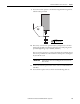
9. Connect the fan power supply wires to the bottom of the fuse holders.
Note that the red wire (+DC) is connected to the left side terminal and
the black wire (-DC) is connected to the right side terminals.
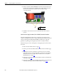
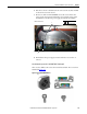
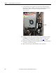
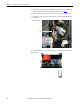
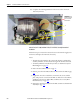
10. Install the new main DC fans in the fan housings using the M5 x 10 mm
POZIDRIV screws supplied in the kit. Final torque is 3.5 N
•m (31.0
lb
•in). See Remove the Main Fan Assembly on page 198 for details.
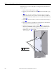
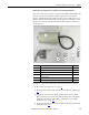
11. Remove the backing from the drive modification label and attach the label
to the front of a main fan housing.
12. Write “DC fan retrofit” and the installation date on the label.
9
Inverter section shown