
Owner manual

Rockwell Automation Publication PFLEX-IN029B-EN-P - August 2014 199
PowerFlex 700AFE Drive - Frame 10 Procedures Chapter 7
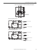
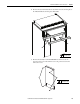
AC Fan Inverter Assembly (20-FI13301) Removal and Installation
PowerFlex 700AFE frame 10 drives have a single fan in the inverter section. The
fan inverter assembly includes the AC fan inverter circuit board, output
transformer, and fan capacitor. See Isolating a Faulty Fan Inverter on page 265
for
test procedures used to determine if the fan inverter assembly requires
replacement. Follow these steps to remove and replace an AC fan inverter
assembly.
1. Review the General Precautions on page 17
.
2. Remove power from the AFE. See Remove Power from the AFE on page
192
.
3. If applicable, move the control frame, and remove the screens, airflow
plate, and protective covers from the AFE. See Move the Control Frame,
and Remove the Screens, Airflow Plate, and Protective Covers (IP21 -
Rittal Enclosure) on page 193
.
4. Remove the main fan assembly from the AFE. See Remove the Main Fan
Assembly on page 198
.
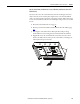
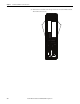
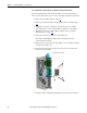
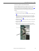
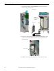
5. Disconnect the fan inverter cables from the connections on the front of
the power structure.
6. Push the fan inverter cables and connectors, largest first, through the
rubber grommet into the frame, where the main cooling fan was located.
5
6