
Owner manual

196 Rockwell Automation Publication PFLEX-IN029B-EN-P - August 2014
Chapter 7 PowerFlex 700AFE Drive - Frame 10 Procedures
ASIC Circuit Board Assembly Cooling Fan (20-PP01096) Removal and Installation
PowerFlex 700AFE frame 10 drives have an ASIC circuit board located in the
inverter section. Follow these steps to remove and replace the ASIC circuit board.
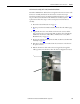
1. Review the General Precautions on page 17
.
2. Remove power from the AFE. See Remove Power from the AFE on page
192
.
3. If applicable, move the control frame, and remove the screens, airflow
plate, and protective covers from the AFE. See Move the Control Frame,
and Remove the Screens, Airflow Plate, and Protective Covers (IP21 -
Rittal Enclosure) on page 193
.
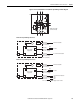
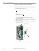
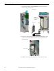
4. Remove the -DC bus connection from the ASIC cover.
Note: When reinstalling the ASIC board, verify that the -DC bus
connection has been made.
5. Remove the four screws that secure the ASIC cover to the ASIC assembly
and remove the ASIC cover.
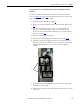
6. Disconnect the fan supply wire from connector X1 on the ASIC circuit
board and remove the fan.
7. Install the ASIC cooling fan and assembly in the reverse order of removal.
4
4
5
Note: Inverter section shown