
Owner manual


Rockwell Automation Publication PFLEX-IN029B-EN-P - August 2014 19
Chapter 1
PowerFlex 700H and 700S Drives - Frame 9
Procedures
This chapter contains spare part information and procedures for testing and
replacing fan system components for frame 9 PowerFlex 700H and 700S drives.
See Appendix A PowerFlex 700H and 700S Diagnostic Procedures on page 255
for additional component test procedures.
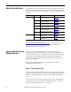
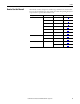
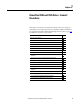
Topic Page
Frame 9 Fan System Spare Parts 20
Tools Needed for Frame 9 Fan System Repairs 20
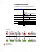
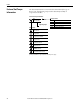
Frame 9 Schematic Diagrams 21
Frame 9 Fan System Replacement Procedures 22
Remove Power from the Drive 23
Remove the Lower Protective Cover 24
Remove the Upper Protective Cover 24
Removing the Main Fan Inverter Capacitor Bracket 25
Main Fan Fuses (20-PP20202) and Fuse Holder (20-PP20300) Removal and
Installation
29
Main Fan Inverter Cooling Fan (20-PP01049) Removal and Installation 30
Main AC Fan Inverter Capacitor (SK-H1-FANCAP-F9) Removal and Installation 31
Main AC Fan Inverter Circuit Board Assembly (20-VB00299) Removal and Installation 33
Main DC Fan Power Supply Circuit Board (SK-H1-DCFANBD1) Removal and Installation 36
AC to DC Fan System Retrofit Kit (SK-H1-DCFANRETROFIT-F9) 39
Main AC Fan (20-PP01080) and Main DC Fan (SK-Y1-DCFAN1) Assembly Removal and
Installation
43
Main AC Fan Inverter Output Transformer (20-PP09055) Removal and Installation 49
Chassis Stirring Fan (20-PP01068) Removal and Installation 50
Cross-plate Stirring Fan (20-PP01068) Removal and Installation 51
Internal Stirring Fan (20-PP01068) Removal and Installation 52