
Owner manual

182 Rockwell Automation Publication PFLEX-IN029B-EN-P - August 2014
Chapter 6 PowerFlex 700H and 700S Drives - Frame 14 Procedures
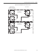
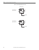
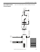
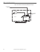
Frame 14 System Diagrams
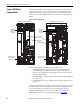
The PowerFlex 700H and PowerFlex 700S frame 14 drive can be configured with
either AC or DC (common bus) input voltage applied. The AC input drives have
both parallel converter and parallel inverter sections, while the DC input drives
have only parallel inverters. The schematics will change based on this hardware
configuration. Tab le 4
provides a list of system diagrams applicable to each drive
configuration.
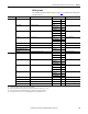
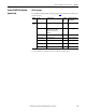
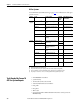
Table 4 - Drive Configurations and Applicable System Diagrams
Please see Frame 13 AFE Schematic Diagrams on page 125 for more information.
Drive Input Voltage Drive Hardware Section AC Fan Systems DC Fan Systems
AC System Figure 18 on page 183
Converter n/a n/a
Inverter n/a n/a
DC System Figure 19
on page 184
Converter n/a n/a
Inverter n/a n/a