
Owner manual

Rockwell Automation Publication PFLEX-IN029B-EN-P - August 2014 175
PowerFlex 700H and 700S Drives - Frame 13 Procedures Chapter 5
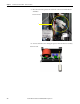
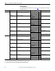
AC Fan: If the measurements are not similar to those in this table, replace
the AC fan.
DC Fan: If the measurements are not similar to those in this table, replace
the DC fan.
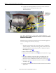
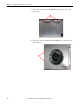
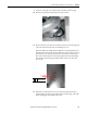
6. For AC fan systems, install the new fan assembly in the reverse order of
removal. For DC fan systems, complete the remaining steps.
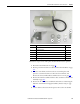
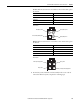
Connection wires Resistance ±5%
Black-Brown 62 Ω
Brown-Blue 36 Ω
Blue-Black 27 Ω
Green-chassis 0 Ω
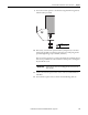
Connection wires Resistance ±5%
Red-Blue ∞ Ω
Red-White ∞ Ω
White-Yellow ∞ Ω
Blue-White ∞ Ω
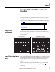
Blue (Motor) Pin 4
Green/Yellow (Ground) Pin 1
Brown (Motor) Pin 3
Black (Motor) Pin 2
AC Fan Pinouts
White (Tach Output) Pin 3
Red (+) Pin 1
Blue (-) Pin 4
Yellow (Control Output) Pin 2
DC Fan Pinouts