
Owner manual

Rockwell Automation Publication PFLEX-IN029B-EN-P - August 2014 163
PowerFlex 700H and 700S Drives - Frame 13 Procedures Chapter 5
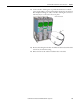
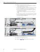
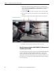
6. Remove the wire harness that connects the fans on the converter and
inverter units.
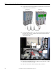
7. Remove the AC fan inverter assemblies. See Main AC Fan Inverter Circuit
Board (20-VB00299) and DC Fan Power Supply Circuit Board (SK-H1-
DCFANBD1) Removal and Installation (Converter Only) on page 148
.
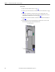
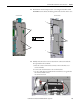
8. Remove the AC fan capacitor from the converter. See Main AC Fan
Inverter Capacitor (SK-H1-FANCAP-F1314) Removal and Installation
(Converter Only) on page 169
.
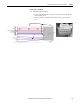
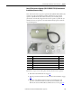
9. Remove the M4 x 8 mm grounding screw (#1 in image) for the AC fan
power conditioning capacitors from the drive.
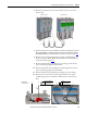
10. Remove the M4 x 25 mm mounting screw (#2 in image) for the AC fan
power conditioning capacitors from the drive.
11. Remove the M8 x 70 mm transformer mounting screw (#3 in image)
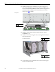
12. Remove the fan extension wire (#4 in image) and remove the power
conditioning capacitors, transformer, and fan extension wire from the
drive.
6
Converter Section Inverter Section
11 10 912
P2
1.0 N
•m (8.8 lb•in)
5.5 mm or HOP6 bit
10 N
•m (88.5 lb•in)
AC Fan System
Converter Section