
Owner manual

Rockwell Automation Publication PFLEX-IN029B-EN-P - August 2014 153
PowerFlex 700H and 700S Drives - Frame 13 Procedures Chapter 5
Main DC Fan Power Supply Circuit Board (SK-H1-DCFANBD1) Removal
and Installation (Inverter Only)
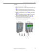
PowerFlex 700H and 700S frame 13 drives have multiple fans power supplies.
You can retrofit an existing AC fan system or replace a DC fan system with a new
DC fan system. See Energy-related Products Fan Efficiency Directive on page 12
for guidelines on replacing an existing fan system with a new DC fan system.
Follow these steps to remove and replace an existing DC fan power supply circuit
board with a new DC fan power supply circuit board.
1. Review the General Precautions on page 17
.
2. Remove power from the drive. See Remove Power from the Drive on page
134
.
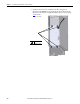
3. Move the control frame, and remove the screens, airflow plates, and
protective covers from the drive. See Move the Control Frame, and
Remove the Screens, Airflow Plates, and Protective Covers on page 135
.
4. Remove the main fan assembly from the drive. See Remove the Main Fan
Assembly on page 143
.
5. Remove the DC fan power supply assembly from the drive. See Removing
the Main AC or DC Fan Power Supply Assemblies (Inverter Only) on
page 145
.
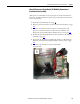
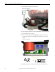
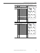
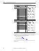
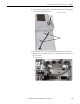
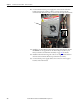
6. Disconnect the wire cable harness from connectors X2, X3, X8, and X81
on the Dc fan power supply circuit board.
7. Remove two M4 x 8 mm POZIDRIV screws that secure the DC fan
inverter circuit board and heatsink to the assembly carriage. Then carefully
remove the circuit board from the assembly.
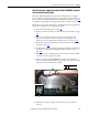
8. Install the DC fan power supply circuit board in the reverse order of
removal.
PZ2
3.0 N
•m (26.5 lb•in)
6
7