
Owner manual

Rockwell Automation Publication PFLEX-IN029B-EN-P - August 2014 137
PowerFlex 700H and 700S Drives - Frame 13 Procedures Chapter 5
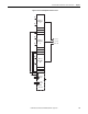
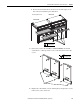
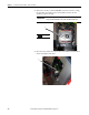
6. Remove the four hexalobular screws that secure the air flow plate to the
drive enclosure and slide the plate off the drive.
7. If necessary, remove the four M5 x 16 mm POZIDRIV screws that
secure the two or three protective covers to the drive, then remove the
covers.
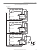
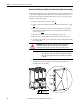
8. Replace the control frame, screens, airflow plates, and protective covers
in the reverse order of removal.
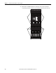
5
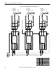
Converter unit
Inverter unit
Note: AC input drive shown
T20
3.0 N•m (27 lb•in)
DC BUS CONDUCT
ORS AND CAPA
CITORS
OPERATE AT HIGH
VOL
TAGE. REMO
VE POWER
AND WAIT 5 MINUTES BE
FORE SER
VICING
DANGER
!
DC BUS CONDUCT
ORS AND CAPA
CITORS
OPERATE AT HIGH
VOL
TAG
E. REMO
VE POWER
AND W
AIT 5 MINUTES BEFORE SER
VICING
DANGER
!
DC BUS CONDUCT
ORS AND CAPA
CITORS
OPERATE AT HIGH
VOL
TAGE. REMO
VE POWER
AND W
AIT 5 MINUTES BEFORE SER
VICING
DANGER
!
2 or 3 covers
6
PZ2
1.65 N•m (14.6 lb•in)