
Owner manual

126 Rockwell Automation Publication PFLEX-IN029B-EN-P - August 2014
Chapter 5 PowerFlex 700H and 700S Drives - Frame 13 Procedures
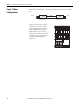
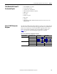
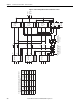
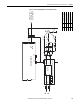
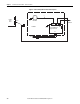
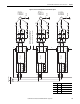
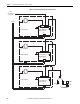
Figure 10 - Frame 13 AC Input Drive Converter and Inverter Sections
Fan
Rectifier Bd.
L1
L3
L2
NFE 3
(1)
X3
X8
X6
X201
Fan
Rectifier Bd.
L1
L3
L2
NFE 2
(1)
X3
X8
X6
X201
Fan
Rectifier Bd.
L1
L3
L2
NFE 1
(1)
X3
X8
X6
X201
F10
F11
DC+
DC-
X1 X1 X1
Fan Distribution
Block (Located in
U Phase)
F12
F13
DC+
DC-
DC+
DC-
F14
F15
5
25
26
21
22
23
X9
+24V
0EVA
X15
Charge
Relay
X2
Fan
Gate Driver
Measure L/R
X5
X4
X3
X11
Fan
Gate Driver
Measure L/R
Fan
Gate Driver
Measure L/R
Phase
Module
W
Phase
Module
V
Phase
Module
U
X3
X8
X3
X8
X3
X8
X1
X1
X1
4
3
3
4
U / T1
V / T2
W / T3
ASIC
Board
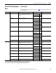
(1) The number of NFE’s varies with the drive
rating as shown in this table:
Voltage
Class Amps
# of
Reactors
Reactor
Connection
# of
NFEs
400
400
400
600
600
600
1150
1300
1450
920
1030
1180
2
3
3
2
2
2
X2
X2
X2
X3
X3
X3
2
3
3
2
2
2
DC+
DC-
DC+
DC-
DC+
DC-
Fan Supply Connection
(Located on the front
of each Converter)
X3
X2