
Owner manual

Rockwell Automation Publication PFLEX-IN029B-EN-P - August 2014 125
PowerFlex 700H and 700S Drives - Frame 13 Procedures Chapter 5
Tools Needed for Frame 13
Fan System Repairs
• #2 POZIDRIV screwdriver
• 19 mm socket wrench
• 5.5 mm hex key or HOP6 bit
• T20 and T25 hexalobular screwdriver
• Multi meter
• Fuse puller
• Needle-nose pliers
• Wire cutter
• Cable ties
• Optional: PowerFlex 700H and 700S maintenance stand (cat. No. 20-
MAINSTND)
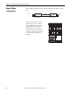
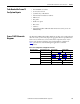
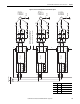
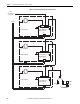
Frame 13 AFE Schematic
Diagrams
The PowerFlex 700H and PowerFlex 700S frame 13 drive can be configured with
either AC or DC (common bus) input voltage applied. The AC input drives have
both converter and inverter sections, while the DC input drives have only an
inverter. The schematics will change based on this hardware configuration.
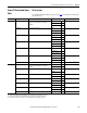
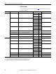
Tabl e 2
provides a list of schematic diagrams applicable to each drive
configuration.
Table 2 - Drive Configurations and Applicable Schematics
Drive Input Voltage Drive Hardware Section AC Fan Systems DC Fan Systems
AC System Figure 10 on page 126
Converter Figure 11 on page 127 Figure 12 on page 128
Inverter Figure 13 on page 129 Figure 14 on page 130
DC System Figure 15 on page 131
Converter n/a n/a
Inverter Figure 16 on page 132 Figure 17 on page 133