
Owner manual

Rockwell Automation Publication PFLEX-IN029B-EN-P - August 2014 121
Chapter 5
PowerFlex 700H and 700S Drives - Frame 13
Procedures
This chapter contains spare part information and procedures for testing and
replacing fan system components for frame 13 PowerFlex 700H and PowerFlex
700S drives. See Appendix A PowerFlex 700H and 700S Diagnostic Procedures
on page 255
for additional component test procedures.
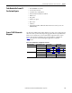
Topic Page
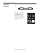
Frame 13 Drive Configurations 122
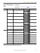
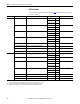
Frame 13 Fan System Spare Parts 123
DC Fan Systems 124
Tools Needed for Frame 13 Fan System Repairs 125
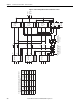
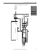
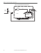
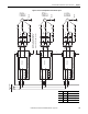
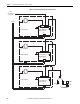
Frame 13 AFE Schematic Diagrams 125
Frame 13 Fan System Replacement Procedures 134
Remove Power from the Drive 134
Move the Control Frame, and Remove the Screens, Airflow Plates, and Protective Covers 135
Remove the Voltage Feedback Circuit Board Assembly (Inverter Only) 138
ASIC Circuit Board Assembly Cooling Fan (20-PP01096) Removal and Installation (Inverter Only) 139
AC or DC Fan System Fuses (20-PP20202) and Fuse Holder (20-PP20300) Removal and Installation 141
Remove the Main Fan Assembly 143
Removing the Main AC or DC Fan Power Supply Assemblies (Inverter Only) 145
Main AC Fan Inverter Circuit Board (20-VB00299) and DC Fan Power Supply Circuit Board (SK-H1-
DCFANBD1) Removal and Installation (Converter Only)
148
Main AC Fan Inverter Circuit Board (20-VB00299) Removal and Installation (Inverter Only) 151
Main AC Fan Inverter Circuit Board (20-VB00299) and DC Fan Power Supply Circuit Board (SK-H1-
DCFANBD1) Removal and Installation (Converter Only)
148
Main DC Fan Power Supply Circuit Board (SK-H1-DCFANBD1) Removal and Installation (Inverter Only) 153
AC to DC Main Fan System (SK-x1-DCFANRETROFIT-F13x and -14x) Retrofit 154
Main AC Fan Inverter Capacitor (SK-H1-FANCAP-F1314) Removal and Installation (Converter Only) 169
Main AC Fan Inverter Capacitor (SK-H1-FANCAP-F1314) Removal and Installation (Inverter Only) 170
Main AC Fan (20-FI13300) and Main DC Fan (SK-Y1-DCFAN1) Assembly Removal and Installation 174