
Owner manual

110 Rockwell Automation Publication PFLEX-IN029B-EN-P - August 2014
Chapter 3 PowerFlex 700H and 700S Drives - Frame 11 Procedures
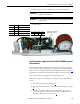
Main AC Fan (20-PP01080) and Main DC Fan (SK-Y1-DCFAN1) Assembly
Removal and Installation
Follow these steps to measure the resistance between the main fan supply wires
and remove and replace the main fan, if necessary.
Notes:
• The fan replacement kit only contains the fan motor and impeller
assembly. Therefore, the sheet metal housing for the fan must be reused.
• To identify which fan is installed in your drive, see Fan Inverter System
Block Diagrams on page 257
.
1. Review the General Precautions on page 17
.
2. Remove power from the drive. See Remove Power from the Drive on page
91
.
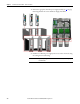
3. Remove the bottom protective cover only from the drive. See Move the
Control Frame and Remove the Air Flow Plate and Protective Covers on
page 92
.
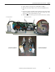
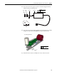
4. Disconnect the fan power supply cable from the bottom of the fan power
supply for the main fan.
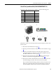
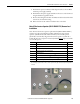
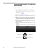
5. Using the appropriate table below, measure the resistance between the fan
supply wires.
AC Fan: If the measurements are not similar to those in this table, replace
the AC fan.
Connection wires Resistance ±5%
Black-Brown 62 Ω
Brown-Blue 36 Ω
Blue-Black 27 Ω
Green-chassis 0 Ω
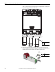
Blue (Motor) Pin 4
Green/Yellow (Ground) Pin 1
Brown (Motor) Pin 3
Black (Motor) Pin 2
AC Fan Pinouts