
Owner manual

Rockwell Automation Publication PFLEX-IN029B-EN-P - August 2014 101
PowerFlex 700H and 700S Drives - Frame 11 Procedures Chapter 3
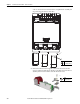
9. Install the AC fan inverter assembly in the reverse order of removal.
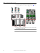
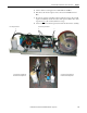
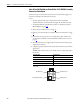
Main DC Fan Power Supply Circuit Board (SK-H1-DCFANBD1) Removal
and Installation
Note: PowerFlex 700H and 700S frame 11 drives have three fan power supplies.
You can retrofit an existing AC fan system or replace a DC fan system with a new
DC fan system. See Energy-related Products Fan Efficiency Directive on page 12
for guidelines on replacing an existing fan system with a new DC fan system.
Note: Retain the fan power supply sheet metal bracket for reuse.
Follow these steps to remove and replace an existing fan system with a DC fan
system.
1. Review the General Precautions on page 17
.
2. Remove power from the drive. See Remove Power from the Drive on page
91
.
3. Move the control frame and remove the air flow plate and protective
covers from the drive. See Move the Control Frame and Remove the Air
Flow Plate and Protective Covers on page 92
.
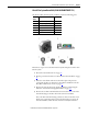
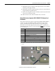
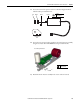
IMPORTANT
Verify that dip switch S1 on the new AC fan inverter board is properly
configured, as shown below.
IMPORTANT
If you are replacing a right-side AC fan inverter circuit board, install the jumper
on connector X3.
S1-1 S1-2 S1-3 S1-4
Off Off On Off
Install Jumper on X3 for Right-
side AC Fan Inverter Board
Switch Setting To indicate the following:
S1 Off 50 Hz fan motor frequency
S2 Off 220 V ac motor voltage
S3 On 230 V ac motor voltage
S4 Off Frame size 9 - 13
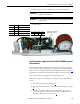
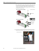
AC Fan System Shown