
Owner manual


2-2 Start Up/Troubleshooting
PowerFlex Diode Bus Supply User Manual
Publication 20T-UM001D-EN-P
Start-Up
Before Applying Power to the Diode Bus Supply
❏ 1. Confirm that all inputs and outputs are connected to the correct
terminals and are properly torqued.
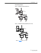
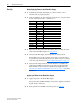
❏ 2. Using an ohmmeter or other continuity testing device, verify that shorts
do not exist between Source 1 and Source 2.
❏ 3. Verify that AC line power at the disconnect device is within the rated
value of the Diode Bus Supply. See Appendix
A.
❏ 4. Verify that the Bus Supply Overtemperature is correctly wired.
This normally closed contact output can be used to set alarms and to
stop the drive(s). Verify that they have been wired correctly according
to the user’s specification. See Control Wiring Examples
on page 1-9.
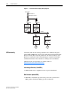
❏ 5. Verify that the jumper between control terminals 12 and GND and
jumper P4 (on DFPS circuit board) are present on grounded supply
lines (default) or removed on non-solid grounded supply lines. See
Disconnecting MOVs and RFI Filter Capacitors
on page 1-10 for more
information.
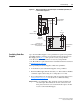
Applying AC Power to the Diode Bus Supply
❏ 1. Apply AC power to the Diode Bus Supply.
The green Power On LED should be on if power is applied to terminals
L1 (R), L2 (S), and L3 (T).
❏ 2. If the green Power On LED is off at this point, see Table 2.A
.
Source 1 Source 2 Checkmark Below if No Short Exists
L1 L2
L1 L3
L2 L3
L1 PE
L2 PE
L3 PE
L1 DC+ Bus
L2 DC+ Bus
L3 DC+ Bus
L1 DC- Bus
L2 DC- Bus
L3 DC- Bus
DC+ Bus DC- Bus
DC+ Bus PE
DC Bus PE