
Owner manual


Installation/Wiring 1-7
PowerFlex Diode Bus Supply User Manual
Publication 20T-UM001D-EN-P
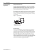
DC Bus Wiring Guidelines
For DC Bus wiring guidelines, refer to AC Drives in Common Bus
Configurations, publication DRIVES-AT002
.
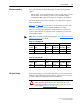
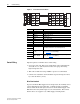
Bus Supply Terminals
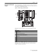
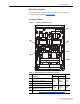
Figure 1.2 Terminal and Jumper Locations
Table 1.C Terminal Specifications and Jumper Information
Item Description
Wire Size Range
(1)
(1)
Maximum/minimum sizes that the terminals will accept - these are not recommendations.
Torque
Maximum Minimum
➊
AC Line Input L1, L2, L3
35 mm
2
(2 AWG)
0.75 mm
2
(18 AWG)
3.3 N•m
(20 lb•in)
➋
PE (Protective Earth) Terminal
➌
DC Bus Terminals (DC+, DC-)
➍
Control Terminals 8…11
2.5 mm
2
(14 AWG)
0.25 mm
2
(22 AWG)
0.8 N•m
(7 lb•in)
➎
Control Terminals 12 and GND
(MOV neutral disconnect; see page 1-10
)
➏
Jumper J4, see Disconnecting MOVs and RFI Filter Capacitors on page 1-10
J4
J1 J2 J6 J3
L1 L2
8
9
11
10
AAAA
AA
DC + DC -
AAA
L1 L2 L3
BB
BB
GND
12
AA
MOV
F1
A
B
A
F2
B
AC
B
B
AC AC
A DC +
A
DC -
V1 V2 V3
FAN1 FAN2
(PE)
➊
➎
➋
➌
➍
➏