PowerFlex Diode Bus Supply User Manual
Important User Information Solid state equipment has operational characteristics differing from those of electromechanical equipment. Safety Guidelines for the Application, Installation and Maintenance of Solid State Controls (Publication SGI-1.1 available from your local Rockwell Automation sales office or online at http:// www.rockwellautomation.com/literature) describes some important differences between solid state equipment and hard-wired electromechanical devices.
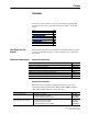
Summary of Changes The information below summarizes the changes made to this manual since its last release (September 2006): Description of Changes Reformatted document from half size (5.5 x 8.5 in.) to full size (8.5 x 11 in.) In Chapter 1: • Revised the subsection “Ambient Operating Temperatures” to include more information. • At the beginning of the section “Power Wiring,” added a recommendation to keep all wired connections identical in size and length to maintain balanced impedance.
soc-ii Summary of Changes Notes: PowerFlex Diode Bus Supply User Manual Publication 20T-UM001D-EN-P
Table of Contents Preface Overview Who Should Use this Manual? . . . . . . . . . . . . . . . . . . . . . . . . . . . . . . . . . . . . . . . . . . . . . Reference Documentation . . . . . . . . . . . . . . . . . . . . . . . . . . . . . . . . . . . . . . . . . . . . . . . . General Drive Information. . . . . . . . . . . . . . . . . . . . . . . . . . . . . . . . . . . . . . . . . . . . . . Specific Drive Information . . . . . . . . . . . . . . . . . . . . . . . . . . . . . . . . . . . . . . . . . . . . .
ii Table of Contents Appendix A Supplemental Information Specifications. . . . . . . . . . . . . . . . . . . . . . . . . . . . . . . . . . . . . . . . . . . . . . . . . . . . . . . . . . . Dimensions . . . . . . . . . . . . . . . . . . . . . . . . . . . . . . . . . . . . . . . . . . . . . . . . . . . . . . . . . . . . AC Input Fusing. . . . . . . . . . . . . . . . . . . . . . . . . . . . . . . . . . . . . . . . . . . . . . . . . . . . . . . . . Fuse Types . . . . . . . . . . . . . . . . . . . . . . . . .
Preface Overview The purpose of this manual is to provide you with the basic information needed to install, start up, and troubleshoot the PowerFlex™ Diode Bus Supply.
P-2 Overview For PowerFlex® 700H Drive PowerFlex® 700S Drive PowerFlex® 750-Series AC Drive See PowerFlex 700H Installation Instructions PowerFlex 700H Programming Manual PowerFlex 700S with Phase I Control Installation Manual (Frames 1…6) PowerFlex 700S with Phase I Control Installation Manual (Frames 9 and 10) PowerFlex 700S with Phase I Control User Manual (All Frame Sizes) PowerFlex 700S with Phase I Control Reference Manual PowerFlex 700S with Phase II Control Installation Manual (Frames 1…6) Power
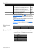
Overview General Precautions ! ! ! ! ! ! P-3 ATTENTION: The Diode Bus Supply contains electrostatic discharge (ESD) sensitive parts and assemblies. Static control precautions are required when installing, testing, servicing or repairing this assembly. Component damage may result if ESD control procedures are not followed. If you are not familiar with static control procedures, see Guarding Against Electrostatic Damage, publication 8000-4.5.2, or any other applicable ESD protection handbook.
P-4 Overview Catalog Number Explanation 1-3 4 20T D a b Position Number 5-7 8 9 120 A E c d e a Product Code 20T Type PowerFlex Diode Bus Supply b Voltage Rating Code D E Input Voltage 240/480V AC 500/600V AC Phase 3 3 DC Output 325…650V DC 675…810V DC c Current Rating Code 120 (1) Frame (1) Output 120.0 Amp 2 PowerFlex 700 drive equivalent frame size.
Overview Description and Schematic Diagram P-5 The Diode Bus Supply is a single-direction power converter for the front end of common DC bus drive systems. It converts the incoming 3-phase AC line voltage to a common DC bus voltage. Figure P.
P-6 Overview Notes: PowerFlex Diode Bus Supply User Manual Publication 20T-UM001D-EN-P
Chapter 1 Installation/Wiring This chapter provides information on the installation and wiring of the PowerFlex Diode Bus Supply.
1-2 Installation/Wiring Minimum Mounting Clearances No Adhesive Label on Top With Adhesive Label on Top 100 (4) 50 (2) 100 (4) 100 (4) 50 (2) 100 (4) Dimensions are in millimeters and (inches). See Appendix A for detailed dimension information. Ambient Operating Temperatures The Diode Bus Supply is designed to operate at 0…40 °C (32…104 °F) ambient without derating. Remove the label from the top to operate the Diode Bus Supply in ambients 41 °C up to 50 °C (104 °F up to 122 °F).
Installation/Wiring AC Supply Source Considerations 1-3 The Diode Bus Supply is suitable for use on a circuit capable of delivering a short circuit rating up to a maximum of 200,000 rms symmetrical amperes, and a maximum of 600 volts. ! ATTENTION: To guard against personal injury and/or equipment damage caused by improper fusing or circuit breaker selection, use only the recommended line fuses/circuit breakers specified in Appendix A.
1-4 Installation/Wiring General Grounding Requirements Safety Ground Terminal - PE The Safety Ground terminal (PE) must be connected to the building grounding scheme. Ground impedance must conform to the requirements of national and local industrial safety regulations and/or electrical codes. This is the safety ground for the Diode Bus Supply. The integrity of all ground connections should be periodically checked.
Installation/Wiring Maximum Loading 1-5 To avoid overloading the Diode Bus Supply, the following requirement applies: The DC Input current sum (Normal Duty or Heavy Duty rating at 40 °C/ 104 °F) of the connected drive(s) must not exceed the Bus Supply continuous DC Bus output current rating of 120 amps at 40 °C/104 °F. For the DC Input Current values of the drives, see tables in the respective drive documentation. Table 1.A and Table 1.B provide guidance on the nominal operation of the Diode Bus Supply.
1-6 Installation/Wiring Power Wiring ! ATTENTION: National Codes and standards (NEC, VDE, BSI, etc.) and local codes outline provisions for safely installing electrical equipment. Installation must comply with specifications regarding wire types, conductor sizes, and disconnect devices. Failure to do so may result in personal injury and/or equipment damage.
Installation/Wiring 1-7 DC Bus Wiring Guidelines For DC Bus wiring guidelines, refer to AC Drives in Common Bus Configurations, publication DRIVES-AT002. Bus Supply Terminals Figure 1.2 Terminal and Jumper Locations ➏ J4 J1 J2 ➌ J6 J3 L1 A A A A A ➊ L2 A A A A A A DC + DC - B B ➍ L1 L2 L3 12 GND 8 9 10 11 MOV B B A A F1 F2 B AC AC B AC A B B DC + ➋ (PE) DC - A V1 ➎ V2 FAN1 V3 FAN2 Table 1.
1-8 Installation/Wiring Figure 1.
Installation/Wiring 1-9 Control Wiring Examples Figure 1.4 Multiple Drives, Running Simultaneously 115V K1 K1 10 Run K1M PowerFlex Diode Bus Supply >°C F1, F2 11 K1 DC Bus K1M Figure 1.
1-10 Installation/Wiring Disconnecting MOVs and RFI Filter Capacitors The Diode Bus Supply contains protective MOVs, and input filter and common mode capacitors that are referenced to ground. To prevent damage, the MOVs should be disconnected from ground if the Bus Supply is installed on any non-solid grounded distribution system where the line-to-ground voltages on any phase could exceed 125% of the nominal line-to-line voltage.
Installation/Wiring Figure 1.6 1-11 Removing the Phase-to-Ground Jumpers for the MOV, Input FIlter, and Common Mode Capacitors TB1 R / L1 To Diode Bridge Rectifier Unit S / L2 T / L3 PE MOVs Ground Jumper 12 Input Filter Capacitors Input Filter and Common Mode Capacitors Ground Jumper Paralleling Diode Bus Supplies To +DC, -DC GND MOV J3 7 4 1 Power Supply Board DFPS 1 J2 4 J4 Common Mode Capacitors Up to two Diode Bus Supplies can be paralleled for operation.
1-12 Installation/Wiring Figure 1.7 Parallel Diode Bus Supply Wiring Diagram Power Input Main Switch or Main Input Contactor Line Reactor Diode Bus Supply Line Reactor Diode Bus Supply DC Bus CE Conformity AC - Drive 1 AC - Drive 2 M 3 M 3 Conformity with the Low Voltage (LV) Directive and Electromagnetic Compatibility (EMC) Directive has been demonstrated using harmonized European Norm (EN) standards published in the Official Journal of the European Communities.
Installation/Wiring 1-13 Harmonic Emissions Electronic converters such as the Diode Bus Supply can cause conducted low frequency disturbances (harmonic emissions) to the supply network. The mandatory three-phase AC line reactors will substantially reduce harmonic currents produced by the Bus Supply. However, the magnitude of the harmonic currents and resulting harmonic voltages depends upon the network impedance at the point where the unit is connected to the network.
1-14 Installation/Wiring 3. Review important precaution/attention statements throughout this document before installing the drive(s). 4. Ground as described in General Grounding Requirements on page 1-4. 5. Control wiring and DC bus wiring leaving the cabinet must be a braided, shielded cable with a coverage of 75% or better, metal conduit or equivalent attenuation.
Chapter 2 Start Up/Troubleshooting This chapter provides the necessary information for the start up and troubleshooting of the Diode Bus Supply. Topic Start-Up Power On LED Troubleshooting ! Page 2-2 2-3 2-3 ATTENTION: Power must be applied to the Diode Bus Supply and the drive to perform the following start-up procedure. Some of the voltages present are at incoming line potential.
2-2 Start Up/Troubleshooting Start-Up Before Applying Power to the Diode Bus Supply ❏ 1. Confirm that all inputs and outputs are connected to the correct terminals and are properly torqued. ❏ 2. Using an ohmmeter or other continuity testing device, verify that shorts do not exist between Source 1 and Source 2.
Start Up/Troubleshooting Power On LED 2-3 The green Power On LED is visible through the front panel and will illuminated if power is applied. ! ATTENTION: The Power On LED is only operational when the unit is energized. Servicing energized equipment can be hazardous. Severe injury or death can result from electrical shock, burn, or unintended actuation of the controlled equipment. Follow safety-related practices of NFPA 70E, Electrical Safety For Employee Workplaces.
2-4 Start Up/Troubleshooting Notes: PowerFlex Diode Bus Supply User Manual Publication 20T-UM001D-EN-P
Appendix A Supplemental Information This appendix provides electrical, environmental, functional, and physical specifications for the Diode Bus Supply, and selection tables for AC input devices.
A-2 Supplemental Information Category Specification Approvals and Standards Compliance NFPA 70 NEMA ICS 3.1 NEMA 250 IEC 146 c UL ® - US National Electrical Code - Safety standards for Construction and Guide for Selection, Installation and Operation of Adjustable Speed Drive Systems. - Enclosures for Electrical Equipment - International Electrical Code US UL and cUL Listed to UL508C and CAN/CSA-C2.2 No.
Supplemental Information Dimensions A-3 The overall and mounting dimensions for the Diode Bus Supply are shown in Figure A.1. Figure A.1 Diode Bus Supply Dimensions (equivalent to PowerFlex 700 Frame 2 Drive) Dimensions are in millimeters and (inches). 222 (8.74) 15 (0.59) 192 (7.56) Ø 5.8 (0.23) 5.5 (0.22) 200 (7.87) 342.5 (13.48) 320 (12.6) 8.0 (0.31) 5.5 (0.22) Front View Side View 151 (6.03) 111 (4.37) Ø 50.5 (2.0) for Gland M50 71 (2.83) Ø 16.5 (0.66) for Gland M16 141 (5.63) 115 (4.
A-4 Supplemental Information AC Input Fusing Table A.A below provides output ampere ratings for the Diode Bus Supply (including continuous, 1 minute, and 3 seconds) and recommended AC line input fusing information. The short circuit protection fuses are acceptable for UL and IEC requirements. Sizes listed are recommended sizes based on 40 °C (104 °F) and the U.S. NEC. Other country, state or local codes may require different ratings. Fuse Types Refer to the recommended types listed below.
Supplemental Information Line Reactors A-5 A minimum reactance is required to limit peak currents in the AC line and the diode bridge circuit. This can be accomplished either by a matched supply transformer or by adding line reactors to ensure the requested minimum voltage drop over the total line impedance. The preferred method is to install a minimum 3% line reactor, which will also reduce line harmonics. Use Table A.
A-6 Supplemental Information Notes: PowerFlex Diode Bus Supply User Manual Publication 20T-UM001D-EN-P
Appendix B History of Changes Topic 20T-UM001C-EN-P, September 2006 Page B-1 This appendix summarizes the revisions to this manual, starting with revision C. Reference this appendix if you need information to determine what changes have been made across multiple revisions. This may be especially useful if you are deciding to upgrade your hardware or software based on information added with previous revisions of this manual.
B-2 History of Changes Notes: PowerFlex Diode Bus Supply User Manual Publication 20T-UM001D-EN-P
Index A AC input line reactors, A-5 voltages, A-1 AC supply grounding, 1-4 non-solid grounded, 1-3 source considerations, 1-3 unbalanced, 1-3 ambient operating temperature, 1-2 B before applying power, 2-2 C cable trays, 1-6 E earthing, see grounding ESD, static discharge, P-3 F filter - RFI, 1-4 fusing, AC input, 1-5 G general precautions, P-3 grounding bus, 1-4 conductor, 1-4 general, 1-4 impedance, 1-4 safety, PE, 1-4 catalog number explanation, P-4 CE conformity, 1-12 checklist, start-up, 2-2 clea
Index-2 removing cover, 1-1 RFI filter grounding, 1-4 T technical support, P-2 troubleshooting, 2-3 S safety ground, 1-4 short circuit protection, 1-5 U unbalanced/non-solid grounded supply, 1-3 spare parts, A-5 specifications, A-1 to A-2 start-up checklist, 2-2 static discharge, ESD, P-3 status indicator, Power On, 2-3 supply source for AC, 1-3 system grounding, 1-4 PowerFlex Diode Bus Supply User Manual Publication 20T-UM001D-EN-P W web site related documentation, P-2 Rockwell Automation technical
Rockwell Automation Support Rockwell Automation provides technical information on the Web to assist you in using its products. At http://www.rockwellautomation.com/support/, you can find technical manuals, a knowledge base of FAQs, technical and application notes, sample code and links to software service packs, and a MySupport feature that you can customize to make the best use of these tools.