
Owner's manual

88 Rockwell Automation Publication 20P-UM001I-EN-P - February 2013
Chapter 2 Drive Start Up
Before Applying Power to the
Drive
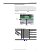
Verify all Drive Configuration Settings
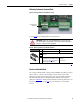
1. With the bottom cover removed from the drive (see Removing the
Drive Covers on page 28
), verify that DIP switch S14 is set correctly to
be ≥ the rated field current specified on the motor nameplate. See
Table 15
on page 61.
2. Verify all switch settings (S9, S10, and S11) for the analog inputs. See
Table 26
on page 73.
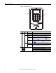
3. Verify all DIP switch and jumper settings for the digital encoder or
analog tachometer feedback device. See Table 2 6
on page 73 and
Figure 50
on page 74.
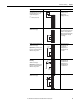
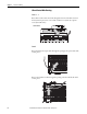
Verify the Power Wiring
• Verify that the AC line power at the disconnect device is within the rated
value of the drive and that all power wiring is correct. See Power Wiring on
page 45
for further information.
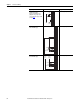
Verify the Control and I/O Wiring
1. Verify that control power and I/O wiring is correct. A digital input (1…8
only) must be wired and configured as a drive enable. See Control
Circuit Input Power on page 65
and I/O Wiring on page 77 for further
information.
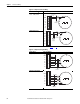
2. If you are using a PTC thermistor or thermal switch to protect the
motor from overloading, remove the 1 k
Ω resistor between terminals 78
and 79. See Thermistors and Thermal Switches on page 62
ATTENTION: The Drive can overspeed if DIP switch S4 is set incorrectly, or the
tachometer is wired incorrectly. Failure to observe this precaution could result in
damage to, or destruction of, the equipment.
ATTENTION: Do not connect any external power to the armature output
terminals, personal injury and/or equipment damage can occur.