
Owner's manual

Rockwell Automation Publication 20P-UM001I-EN-P - February 2013 85
Installation and Wiring Chapter 1
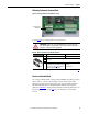
DC Analog Tachometer Terminal Block
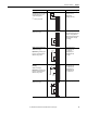
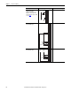
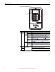
Figure 56 - Analog Tachometer Terminal Block Location
See page 214 for DC Analog Tachometer specifications.
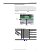
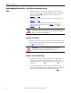
Table 38 - DC Analog Tachometer Terminal Designations
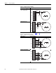
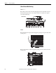
Resolver Feedback Module
The resolver feedback module (catalog number 20P-RES-A0), which provides a
drive interface to a selection of compatible resolvers, must be ordered and
purchased separately from the drive. The resolver option module includes the
PowerFlex DC Drive Resolver Feedback Module Installation Instructions,
publication 20P-IN071
, which provides installation and wiring information. See
Resolver Type Selection on page 283
for more information on compatible
resolvers.
ATTENTION: The drive can overspeed if DIP switch S4 is set incorrectly, or the
tachometer is wired incorrectly. Failure to observe this precaution could result in
damage to, or destruction of, the equipment.
Label Signal Description
– Negative input –
A
(Not Used)B
C
+ Positive input
See Verify Motor Rotation and Run Feedback
Polarity Checks on page 99
for information
on determining feedback polarity.
22.7 / 45.4 / 90.7 / 181.6 / 302.9V
(1)
max voltage
8 mA max. current
(1) Maximum voltage depends on the configuration of DIP switch S4. See DC Analog Tachometer DIP Switch S4 Example on page 74.
Analog Tachometer
terminal block
A
B
C
+
−