
Owner's manual

Rockwell Automation Publication 20P-UM001I-EN-P - February 2013 83
Installation and Wiring Chapter 1
Digital Encoder Terminal Block
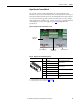
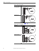
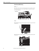
The encoder connection cables should always be connected directly to the
terminals on the encoder terminal block. The encoder cable must be made up of
twisted pairs with the shield connected to the shield ground on the drive side. Do
not connect the shield to ground on the motor side. In some cases (for example,
cable lengths that exceed 100 meters), it may be necessary to ground the shield of
each twisted pair on the power supply. See page 214
for Digital Encoder
specifications.
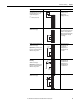
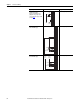
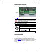
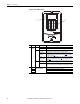
Figure 53 - Digital Encoder Terminal Block Location
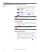
Table 37 - Digital Encoder Terminal Designations
Terminal Block Label Signal
Description
A+ Encoder A Single channel A or dual channel
quadrature A input
A- Encoder A (NOT)
B+ Encoder B Single channel B or dual channel
quadrature B input
B- Encoder B (NOT)
Z+ Encoder Z Pulse, marker or registration input
(2)
(2) Selectable via switch S20 on the control board. See Tab le 26 on page 54.
Z- Encoder Z (NOT)
COM +5/12…15V
(1)
DC Return Internal power common
+V +5/12…15V
(1)
DC Power
(1) Selectable via switch S21 on the control board. See Tab le 26 on page 54.
Internal power source
200 mA
Digital Encoder
terminal block
Control board
EMI shield
Wire shield ground
Wire shield ground
A-
B+
B-
Z+
A+
COM
+V
Z-